CONSOLE
POWER
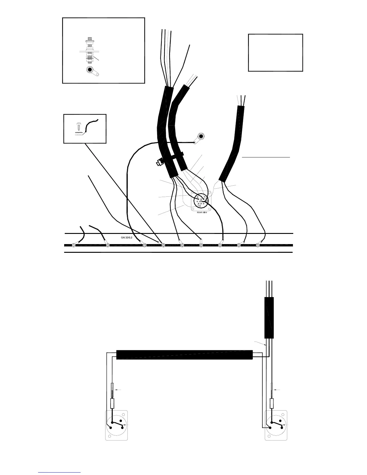
WIRING
2x GN 32/0.2
TO MASTER CONN
PCB (AG2627)
TO MONO PCB
GN 24/0.2
GN 24/0.2
GN 32/0.2GN 24/0.2 GN 24/0.2 GN 24/0.2
BL 16/0.2
BK 24/0.2
RED 24/0.2
GY 16/0.2
BN 16/0.2
GN 24/0.2
RED 16/0.2
TO MASTER PCB
(AG2626)
TO LITTLITE XLR'S
TO MPU PCB (AG2624)
2BA SOLDER TAG (AK0001)
M5 CRINKLE WASHER (AB0304)
TO MONO PCB (AG2625)
CABLE TIE TO
MASTER CONNECTOR PCB
(AK0151)
DC POWER CONNECTOR
Pin 1 = +16V (RED)
CHASSIS EARTH TERMINAL
CHASSIS
EARTH
TERMINAL
Pin 3 = -16V (BLACK)
Pin 4 = CHASSIS 0V (GREEN/YELLOW)
Pin 5 = AUDIO 0V (GREEN)
Pin 10 = +48V (BLUE)
Pins 2, 6, 7, 8, 9 = not connected
CHASSIS
EARTH BAR
Red
P22
Gn
P20
Gn
P21
Gn
P5
Bk
P2
Bl
P4
Rd
P3
Gn 24/0.2
P2
P3
P2
Refer to LITTLITE
wiring diagram
1
2
3
4
22R 2.5W
TC LINK
TO POWER SKT
GY 16/0.2
GN 16/0.2
BN 16/0.2GN 16/0.2
XLR
2 x 4 PIN XLR
(AL8104)
VIEW FROM BEHIND FRONT PANEL (MIXER UPSIDE DOWN)
LITTLITE 4 PIN XLR WIRING
Refer to console power
wiring drawing
TC LINK
XLR
4
3
1
2
SLEEVING
SLEEVING
Gy
Pin 3
Gn
Pin 4
Bn
Pin 1
22R 2.5W
VIEW FROM BEHIND FRONT PANEL (CONSOLE UPSIDE DOWN)
 Loading...