Do you have a question about the ALLEN & HEATH iLive-T80 and is the answer not in the manual?
Read and follow important safety instructions for equipment operation.
Understand firmware versions and compatibility for iLive features.
Lists additional resources like User Guides and the Allen & Heath website.
Guidelines to avoid cosmetic and functional damage to the iLive system.
Advice on shielding equipment from dirt, heat, and moisture.
Recommended methods for cleaning the iLive system components.
Proper methods for safely transporting the iLive equipment.
Tips for routing cables to prevent stress and tripping hazards.
Warning against removing modules while the system is powered.
Guidance on avoiding extreme heat, direct sunlight, and sub-zero temperatures.
Describes the iLive's modular and fixed format approach for live sound mixing.
Details the MixRack's role as the system's DSP and processing hub.
Explains the Surface's function as a controller with an intuitive user interface.
Lists various methods for controlling and connecting to the iLive system.
Details the iDR10 modular MixRack, its DSP engine, and I/O.
Describes the iDR0 MiniRack, similar to iDR10 but without slots.
Explains the different models and features of modular surfaces.
Information on CAT5 cables for system connection and audio networking.
Describes the optional redundant power supply for iLive systems.
Details the available touring grade flightcases for iLive systems.
Information on compatible PL Series remote controllers.
Overview of the software for system control and offline editing.
Explains the core DSP engine, its architecture, and internal effects.
Describes the module for audio networking and clock distribution.
Explains the CPU module's role in system management and control.
Lists the available slots (K, L, M) for system modules.
Details the built-in 3-port Ethernet switch for network connectivity.
Describes the Port A connector for Surface and breakout audio.
Describes the Port B connector for digital split and expansion.
Details the PL-Anet port for connecting remote controllers.
Describes the 10 slots available for audio input/output modules.
Details the module providing 8 mic/line preamps with remote gain.
Details the module providing 8 balanced line outputs.
Describes the module for 16 inputs via screw terminals with selectable inputs.
Details the module providing 16 digital outputs in various formats.
Details the module providing 4 pairs of digital outputs.
Details the module providing 4 pairs of digital inputs.
Describes the touring grade flight case for MixRacks.
Explains how to use the tool for module removal and reconfiguration.
Details the universal mains power supply module and its backup option.
Notes compatibility with console lamps and recommends Allen & Heath LEDlamp.
Describes the port for connecting an optional redundant power supply.
Details XLR sockets for local audio, talkback, and monitor outputs.
Describes additional USB ports and VGA output for external monitor display.
Details the internal universal mains voltage power module with an on/off switch.
Explains the CPU module for system control, networking, and remote access.
Describes the analogue-style control section for channel processing.
Explains the module for digital audio networking and interfacing.
Describes the TouchScreen for status, setup, and memory management.
Details the 4 slots for optional audio input/output modules compatible with the MixRack.
Describes the 8 user-assignable keys for custom functions.
Details the talkback mic input, level trim, and assignment controls.
Describes the headphone and local monitor output for monitoring.
Describes the Solo-In-Place and PAFL controls for monitoring.
Describes the scene keys for memory management and recall.
Details the elements within a typical control strip: Meter, LCD, Encoder, SEL, PAFL, Mute, MIX, Fader.
Explains the independent groups of fader strips and their layers for control.
Describes Copy/Paste/Reset and other edit keys for scene and channel management.
Describes ALT VIEW, GEQ FADER FLIP, and FREEZE IN LAYERS functions.
Describes Scene GO recall keys and SCENE SAFES for memory protection.
Describes headphone/USB ports and local audio I/O connections.
Describes the Surface to MixRack link (ACE) and additional Ethernet ports.
Lists the different iLive surface models by fader count (iLive-80 to iLive-176).
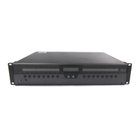
Details the IDR-64, IDR-48, IDR-32, and IDR-16 fixed format MixRacks.
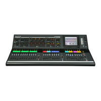
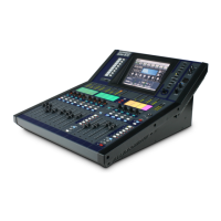
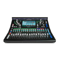
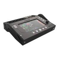
Details the iLive-T112, iLive-T80, and iLive-R72 fixed format Surfaces.
Describes the range of compatible PL Series remote controllers.
Describes high-performance, recallable analogue preamps.
Details line level balanced XLR outputs with headroom.
Information on fitting rack ears into a 19" rack or flightcase.
Describes MIDI IN and OUT sockets for system control.
Details the RS485 connection for PL Series controllers.
Describes the slot for system expansion cards like EtherSound, MADI.
Details the stereo socket for headphone monitoring and PAFL output.
Explains the indicator for MixRack digital audio sync lock.
Explains the single CAT5 link for audio and control between MixRack and Surface.
Details the built-in 3-port switch for connecting network devices.
Describes the analogue-style control section for channel processing.
Explains the strip for naming and color coding channels.
Details the independent groups of fader strips and their layers for control.
Describes the TouchScreen for status, setup, and memory management.
Explains the 8 user-assignable keys for custom functions.
Describes the dimmer control for the TouchScreen.
Details the talkback mic input, level, and assignment.
Describes the PAFL monitor and Solo-In-Place controls.
Explains Copy/Paste/Reset and other edit keys.
Describes ALT VIEW, GEQ FADER FLIP functions.
Explains FREEZE IN LAYERS for keeping channels visible across layers.
Describes Scene GO recall keys and SCENE SAFES for memory protection.
Notes the provision for console lamps.
Describes the VGA port for an external monitor display.
Describes the USB ports for connecting memory keys.
Describes the local monitor output for PAFL signals.
Details the assignable local audio inputs and outputs.
Explains the ACE CAT5 cable link for audio and control.
Describes the MIDI ports for external system control.
Describes extra Ethernet ports for connecting laptops and routers.
Describes the 8 user-assignable keys for custom functions.
Describes the keys for accessing system setup and management.
Explains how to access channel processing via the TouchScreen.
Describes the dimmer control for the TouchScreen.
Details the talkback mic input and level trim.
Describes the rotary control for headphone level.
Explains the strip for naming and color coding channels.
Describes the function to clear active PAFL signals for inputs and outputs.
Details the two groups of fader strips and their layers for control.
Details how to assign talkback to master MIX keys.
Describes controls for mix assignments and pre/post settings.
Explains the ALT VIEW function for channel/socket numbers.
Describes the GEQ FADER FLIP function to display GEQ across faders.
Explains FREEZE IN LAYERS for keeping channels visible across layers.
Describes scene GO recall keys and their default disabled state.
Explains SCENE SAFES to prevent selected channels from being overwritten.
Describes the VGA port for an external monitor display.
Describes the USB ports for connecting memory keys.
Describes the local monitor output for PAFL signals.
Explains the ACE CAT5 cable link for audio and control.
Describes the MIDI ports for external system control.
Describes extra Ethernet ports for connecting laptops and routers.
Describes the power input connector with a clip for securing the cable.
Details the assignable local audio inputs and outputs.
Explains the two main system connections using CAT5 cables for audio and control.
Details the NETWORK port for the control interface to the MixRack.
Describes Port A for audio and EtherSound, used for Surface and breakout devices.
Explains Port B for FOH/Monitor, recording, and system expansion.
Instructions for connecting using the EtherSound standard.
Details the control connection via Ethernet, allowing multiple devices.
Details the audio connection via EtherSound, carrying 64 channels.
Explains the single CAT5 cable for transporting audio and control.
Details how to set up dual redundancy for the ACE link for uninterrupted operation.
Details connecting the Surface to MixRack using ACE ports via CAT5 cable.
Explains default IP addresses and network setup for system connection.
Instructions for connecting a laptop for system control using iLive Editor software.
Details connecting PL Series remote controllers via PL-Anet port.
Step-by-step guide for powering on the iLive system components.
Explains the meaning of the NETWORK Lnk/Act indicators for connection status.
Provides estimates for MixRack, Surface, and TouchScreen boot times.
Instructions for safely shutting down the iLive system.
Describes the fixed audio interface for T Series surfaces for local audio.
Explains the modular surface's audio slots and ports for local audio.
Details the specific audio connections on the T112 Surface.
Details the specific audio connections on T80 and R72 Surfaces.
Details the 8-channel analogue input module with remote gain control.
Describes the XLR input connector, gain range, and preamp converters.
Describes the 8-channel module with dual inputs and screw terminal connectors.
Details the 8-channel balanced line output module for assigning signals.
Describes the module for 8 digital inputs, selectable by format (AES, SPDIF, TOSLINK).
Describes the module for 8 digital outputs, available in multiple formats simultaneously.
Details the 16-output module for various digital formats like ADAT, Aviom, IDR Expander.
Describes the ADAT optical outputs for connecting to ADAT-equipped devices.
Explains connecting iDR expanders for remote analogue or digital outputs.
Describes the interface for Aviom personal monitoring systems.
Details the module for Hear Technologies Hear Back personal monitoring systems.
Explains the CPU module for control, networking, and power status.
Details the built-in 3-port Ethernet switch for network connectivity.
Describes how to reset network addresses to factory defaults.
Details the standard MIDI IN, THRU, and OUT ports for external control.
Describes the port for connecting PL Series remote controllers.
Explains the DSP mix engine, its architecture, and internal effects.
Details the original RAB module for audio networking and clock distribution.
Describes the built-in headphone amplifier with volume control.
Explains the indicator for digital audio sync lock.
Guides on selecting the system's audio clock source (Internal, Remote B, DARS).
Details the available audio network options (EtherSound) for Port A and B.
Describes the older version of the Remote Audio module and its limitations.
Details the newer RAB2 module supporting various networking cards.
Explains the use of Port A on the RAB2 module for linking devices.
Explains the use of Port B on the RAB2 module for expansion.
Describes the BNC connectors for synchronizing audio clocks.
General overview of modules required for modular surfaces.
Details the controller module for the iLive Surface, housing network interfaces.
Explains the module for digital audio interfacing and networking.
Describes the older RAB module supporting only EtherSound.
Details the newer RAB2 module supporting various networking and digital interface cards.
Describes the ACE card for 64-channel bi-directional audio and control link.
Details the EtherSound networking card for multi-channel digital audio.
Describes the Mini Multi Out card for various digital output formats.
Details the MADI networking card for multi-channel audio transmission.
Details the M-ACE card for point-to-point audio and network links.
Explains bridging the network over the ACE cable for control.
Details the primary ACE port connection for linking devices.
Details the secondary ACE port for optional redundant backup connection.
Instructions for fitting the ACE card to specific iDR MixRacks.
Instructions for fitting the ACE card to iDR10 and iLive Surfaces.
Explains the single ACE cable link between Surface and MixRack for audio and control.
Details using the bridge to control networks over the same cable.
Explains transporting other TCP/IP networks through ACE.
Details using a second ACE port for cable redundancy.
Details CAT5e cable standards and recommended types for ACE connections.
Instructions for patching signals to and from Port B using the TouchScreen or Editor.
Details the M-ES-V2 EtherSound card for multi-channel digital audio networking.
Explains EtherSound as a digital audio networking standard from Digigram.
Details CAT5E cable types and lengths for EtherSound connections.
Explains the RX/TX indicators for network link status.
Describes the port for connecting the EtherSound Monitor application.
Explains connecting devices using IN and OUT ports for audio transfer.
Instructions for installing the ES V2 card into the RAB2 module.
Guides on assigning sources and destinations for audio channels via EtherSound.
Details the carrier frame for reusing older AVD EtherSound cards with RAB2.
Describes the original audio network module fitted to early iLive systems.
Details the newer RAB2 module offering wider compatibility and features.
Instructions for fitting the M-ES-V1-BASE frame into the RAB2 module.
Instructions for plugging the Auvitran AVD card onto the carrier frame.
Instructions for attaching the protective foam strip to the card.
Guides on assigning sources and destinations for the audio channels.
Details the Mini Multi Out card for multiple digital output formats.
Describes the ADAT optical outputs for up to 24 track recording.
Explains connecting to iDR expanders or Hearbus hubs via RJ45 ports.
Details connecting to the Aviom personal monitoring system via CAT5 cable.
Instructions for fitting the M-MMO card to specific MixRacks' Port B slot.
Instructions for fitting the M-MMO card to iDR10 and iLive Surfaces' Port A or B slot.
Details assigning signals to Surface Port B outputs for recording.
Notes on fitting M-MMO and assigning outputs for firmware V1.7.
Details the MADI card for multi-channel audio transmission between iLive and MADI equipment.
Instructions for fitting the M-MADI card to specific MixRacks' Port B slot.
Instructions for fitting the M-MADI card to iDR10 and iLive Surfaces' Port A or B slot.
Explains operating with two separate MADI BNC links for simultaneous connection.
Details configuring LINK 1 and LINK 2 as a redundant pair for uninterrupted operation.
Describes the various functions of the AUX BNC connector for system flexibility.
Explains duplicating the output stream from LINK 1 OUT for signal splitting.
Explains duplicating the input stream for daisy-chaining devices.
Describes using an external source to sync the iLive system.
Explains outputting a word clock signal for other systems to sync from iLive.
Details coaxial cable requirements and recommended types for MADI connections.
Describes the iDR-8 and iDR-4 rack mounted mix processors for installed sound systems.
Details the 8-channel output expanders connectable via CAT5.
Describes the range of compatible PL Series remote controllers and their programmability.
Details the PC/MAC software for controlling the iLive system via Ethernet.
Describes the gooseneck lamp with LED array and dimmer.
Details the touring grade CAT5 cable drum with EtherCon connectors.
Describes the optional rack-mounted backup power supply for redundancy.
Details available flight cases for iLive systems and their availability.
Provides dimensions and weights for the MixRack flight case.
Provides dimensions and weights for the iPS10 PSU and iDR0 MiniRack.
Provides dimensions and weights for the iLive Surfaces.
Provides dimensions and weights for the Surface flight cases.
Provides dimensions and weights for the IDR10 MixRack.
Provides dimensions and weights for the T112 Surface.
Provides dimensions and weights for the T80 Surface.
Provides dimensions and weights for the fixed format MixRacks.
Instructions for fitting rack ears with side trims for desk top use.
Instructions for fitting rack ears in a flush mounted configuration.
Instructions for fitting rack ears at a 16-degree angle for a lower profile.
Details dimensions required for adequate ventilation and connector space.
Outlines the terms and conditions of the manufacturer's warranty.
| Type | Digital Mixing Console |
|---|---|
| Channels | 80 |
| Input Channels | 80 |
| Bit Depth | 24-bit |
| Networking | Ethernet |
| Computer Connectivity | USB |
| Expandability | Yes |
| Sample Rate | 96kHz |
| EQ Bands | 4 |
| Metering | LED |
| Fader Configuration | Motorized |
| Processing | DSP |
| Control Surface | Yes |
| Inputs | Analog, Digital |