Do you have a question about the ALLEN & HEATH 14:4:2 MixWizard WZ3 and is the answer not in the manual?
| Type | Analog Mixer |
|---|---|
| Model | MixWizard WZ3 14:4:2 |
| Channels | 14 |
| Buses | 4 |
| Mic Inputs | 8 |
| Line Inputs | 6 |
| Phantom Power | Yes |
| Direct Outputs | Yes |
| Other Inputs | 2 (Stereo) |
| Main Outputs | 2 |
| Other Outputs | 4 |
| EQ Bands | 3 |
| Connectors | XLR, TRS |
Provides technical details for servicing the MixWizard WZ3 14:4:2 mixer.
Lists web resources, contact information, and related documentation for the mixer.
Guidelines for qualified personnel and safe workspace requirements for servicing.
Instructions for connecting equipment to correct mains power and cord safety.
Steps for safely opening and correctly closing the unit after service.
Procedures for testing the unit after service and safely packing for shipping.
Details on PCB technology, operation checks, and fault tracing methods.
Lists historical changes made to assemblies with serial numbers and dates.
Lists product model numbers and part numbers for main assemblies.
Lists part numbers for various PCBs: PSU, Mono, Connector, Group, Stereo, Left, Right, SYS-LINK.
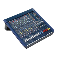
Identifies various knobs, buttons, switches, LEDs, and faders on the surface.
Details on connectors, potentiometers, and associated part numbers.
Identifies rear panel connectors like XLR, Phono, Jack, and Mains IEC.
Details on the mains switch, fuse holder, and power input specifications.
Schematics for Phantom Power, Mic/Line, Dual Stereo, Groups/Aux, Matrix, Monitor, and 2-Track.
Schematics for Talkback Mic input and SYS-LINK connection points.
Details of components like transformer, chokes, bridge rectifier, and ICs.
Designations for power rails (+15V, -15V, +10V, +48V) and connectors (CN1, CN2).
Diagram showing the physical layout of components on the PSU PCB.
Schematic details for input stages, including potentiometers, switches, and ICs.
Identification of resistors, capacitors, LEDs, switches, and jumper settings.
Detailed breakdown of connectors CN100, CN101, CN102, CN103 and their signals.
Schematic details for Insert Send/Return, Line I/O, Microphone, and Direct Output.
Details pin assignments for CN100, CN101 (Jack V5M) and CN102 (Jack V3M).
Schematic for microphone and line signal paths, including phantom power.
Details pin assignments for CN100, CN101 (Jack V5M) and CN102 (Jack V3M).
Schematic for microphone and line signal paths, including phantom power.
Details pin assignments for CN100, CN101 (Jack V5M) and CN102 (Jack V3M).
Schematic for microphone and line signal paths, including phantom power.
Details pin assignments for CN100, CN101 (Jack V5M) and CN102 (Jack V3M).
Schematic for microphone and line signal paths, including phantom power.
Details pin assignments for CN100, CN101 (Jack V5M) and CN102 (Jack V3M).
Schematic for microphone and line signal paths, including phantom power.
Details pin assignments for CN100, CN101 (Jack V5M) and CN102 (Jack V3M).
Schematic for microphone and line signal paths, including phantom power.
Details pin assignments for CN100, CN101 (Jack V5M) and CN102 (Jack V3M).
Schematic for microphone and line signal paths, including phantom power.
Details pin assignments for CN100, CN101 (Jack V5M) and CN102 (Jack V3M).
Schematic for microphone and line signal paths, including phantom power.
Details pin assignments for CN100, CN101 (Jack V5M) and CN102 (Jack V3M).
Schematic for microphone and line signal paths, including phantom power.
Details pin assignments for CN100, CN101 (Jack V5M) and CN102 (Jack V3M).
Schematic for microphone and line signal paths, including phantom power.
Details pin assignments for CN200-CN207 (Jack V5M) and their signal connections.
Schematic showing signal paths for stereo inputs.
Details pin assignments for CN300-CN313 (XLR/Jack) and group/aux outputs.
Schematic for group and auxiliary output signal paths.
Details pin assignments for CN400-CN413 (XLR/RCA/Jack) and master outputs.
Schematic for mix outputs, mono outputs, and 2-track I/O.
Schematic for group inputs (AUX1-4) and outputs (Group 1-4).
Schematic for PFL/AFL signal paths and meter indication.
Schematic for matrix submix, matrix output, and balanced output drivers.
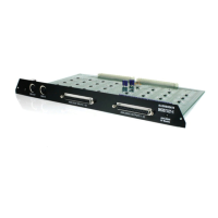
Details of the SYS-LINK connector and its interface to other PCBs.
Schematic for stereo input channels, including potentiometers, switches, and ICs.
Schematic for MIXL, MIXR SUM and MIX circuits.
Schematic for PFL/AFL signal paths and meter indication.
Schematic for mono output and local monitor signal paths.
Schematic for input (AUX5, MIXL) and output (AUX5_OUT, MIXL_OUT) stages.
Schematic for PFL/AFL signal paths and meter indication.
Schematic for noise/oscillator generation and talkback microphone input.
Details of the SYS-LINK connector and its interface to other PCBs.
Schematic for input (AUX6, MIXR) and output (AUX6_OUT, MIXR_OUT) stages.
Schematic for PFL/AFL signal paths and meter indication.
Schematic for mono output and local monitor signal paths.
Schematic detailing LM339 comparator circuits for various functions.
Schematics for SYS-LINK inputs and outputs for Aux, Group, Mix, and PFL signals.
Details of the SYS-LINK connector interface to the master PCB.
Schematic for conditioning input signals for Mix, Group, and PFL paths.
Schematic for buffering output signals for various paths.
Describes changes to TC links and component additions for improved performance.
PCB up-issue from iss.1 to iss.2, changing resistor values for correct levels.
Change in resistors to stabilize pre-amp noise performance.
Modifications to heatsink nutserts and addition of insulating kits.
Change in resistor values for improved audio noise performance.
Up-issue PCB to increase via sizes for better test fixture contact.
PCB up-issue to resolve incorrect normalising function for stereo inputs.
Addition of a TC link to stabilize hum performance.
Changes to capacitor and resistor values for stabilizing pink noise.
PCB up-issue with value changes, component addition, and via size updates.
PCB up-issue to add a power on LED and adjust vias.
Addition of H12 sleeving to prevent shorting on previous TC link mods.
PCB up-issue for performance/reliability with component and value changes.
Adjustments to connector chassis, blanking plate, and tape addition for clearance.
Change in resistors to ensure LEDs turn off with no signal present.
Hand modifications to SYSLINK PCBs to prevent cross talk on group inputs.
Move and add holes in panels for visual enhancement and screw change.
Change in resistors to enhance the performance of the 2-track output.
Changes to heatsink mounting bushes to prevent PCB damage and shorts.