3–13Configuration and Interfacing
Publication 1203–5.1 –– July, 1997
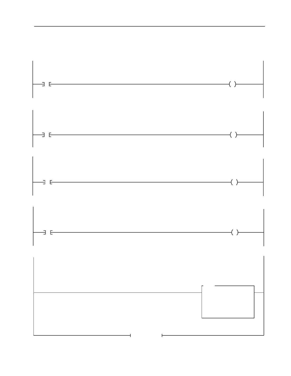
PLC 5/15 Example continued
When the Machine JOG Pushbutton is pressed, the PLC will send a JOG command to the drive. The drive will start and run at the programmed Jog
Frequency if no STOP command is being sent by the PLC or other control device. (Jog button is a normally open contact in this example.)
When the drive is faulted, the PLC will receive a Drive Faulted Status Bit.
Drive Data In A1
(Data to Drive)
N7 : 1
500
0: 022
500
MOV
MOVE
Source
Dest
When the Machine Clear Faults Pushbutton is pressed, the PLC sends a Clear Faults command to the drive. (Clear Faults button is a momentary nor-
mally open contact in this example.)
Drive
Clear Faults
Command
0 : 020
Machine Clear
Faults
Pushbutton
I : 000
03
03
When the Drive is running, the PLC will receive a Drive Running Status Bit.
Machine
Running
Indicator
0 : 000
Drive
Running
Status Bit
I : 020
01
00
Drive
JOG
Command
0 : 020
Machine
JOG
Pushbutton
I : 000
02
02
END OF FILE
Machine
Faulted
Indicator
0 : 000
Drive
Faulted
Status Bit
I : 020
07
01
This rung moves a value from the PLC data table into the drive parameter specified by the Data In A1 parameter of the drive.

 Loading...