1–5Overview
Publication 1203–5.1 –– July, 1997
The remote I/O communications module contains three DIP switches
SW1, SW2, and SW3 (Figure 1.1 and Figure 1.2). Switches are set
On or Off as detailed in Figure 1.4. For a detailed explanation of
switch configuration, refer to Chapter 2, Installation.
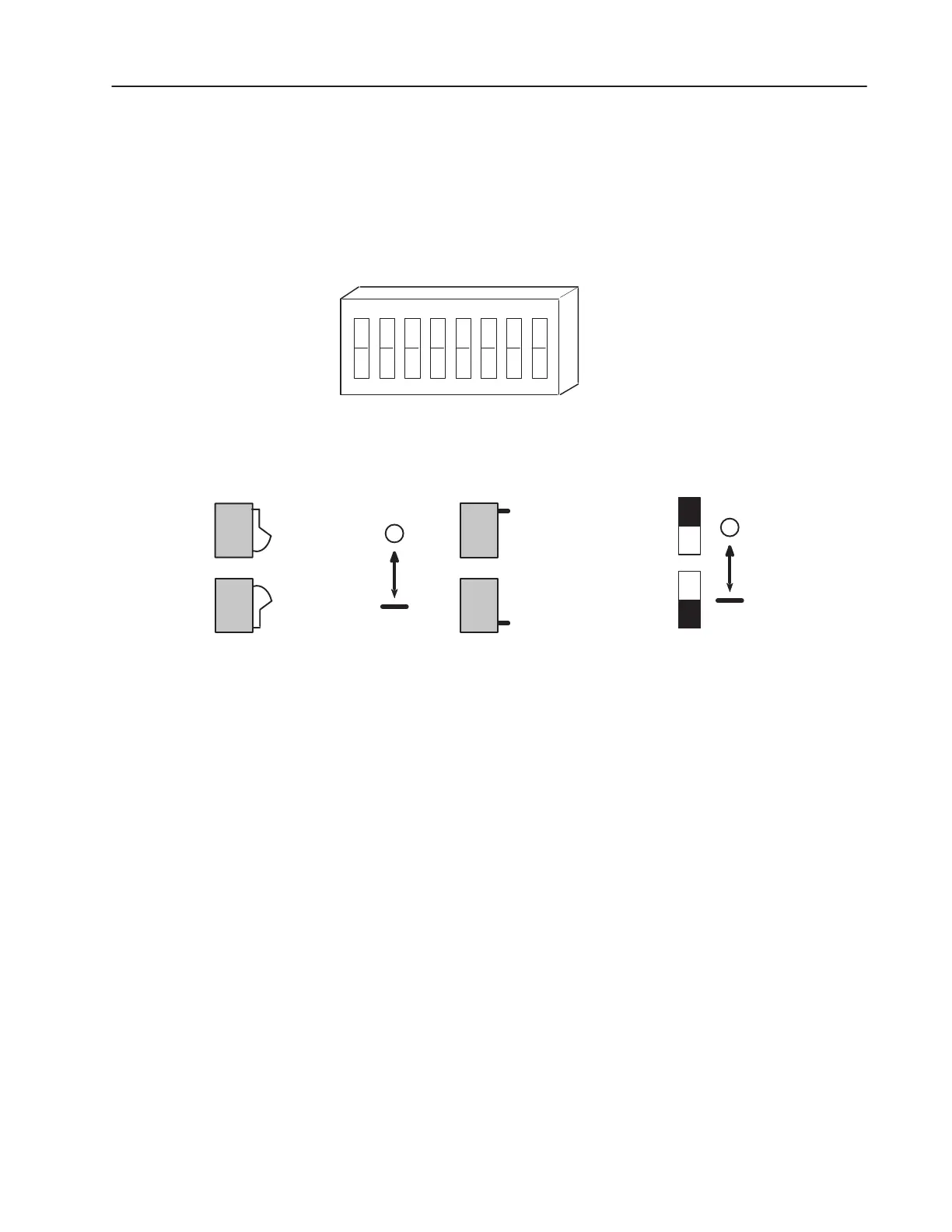
Figure 1.4
Configuration Switch
Side View of Typical Switches
Open
8
Closed (On)
1234
5
67
OPEN
Open
Open (Off)
Rocker Switch
Open
Open
Slide Switch
Switch Designation as
shown in this manual
OFF (OPEN)
ON
Datalinks are a SCANport mechanism for transferring additional
information between a programmable controller and a SCANport
device. Each datalink switch on the adapter reserves two words of
the programmable controller I/O image table. The 1305, 1336
PLUS, and 1336 FORCE drives support this mechanism. For
additional details, refer to Chapter 3, Configuration and Interfacing.
Configuration Switches
Datalinks

 Loading...