Chapter
4
Publication 1203–5.1 –– July, 1997
Troubleshooting
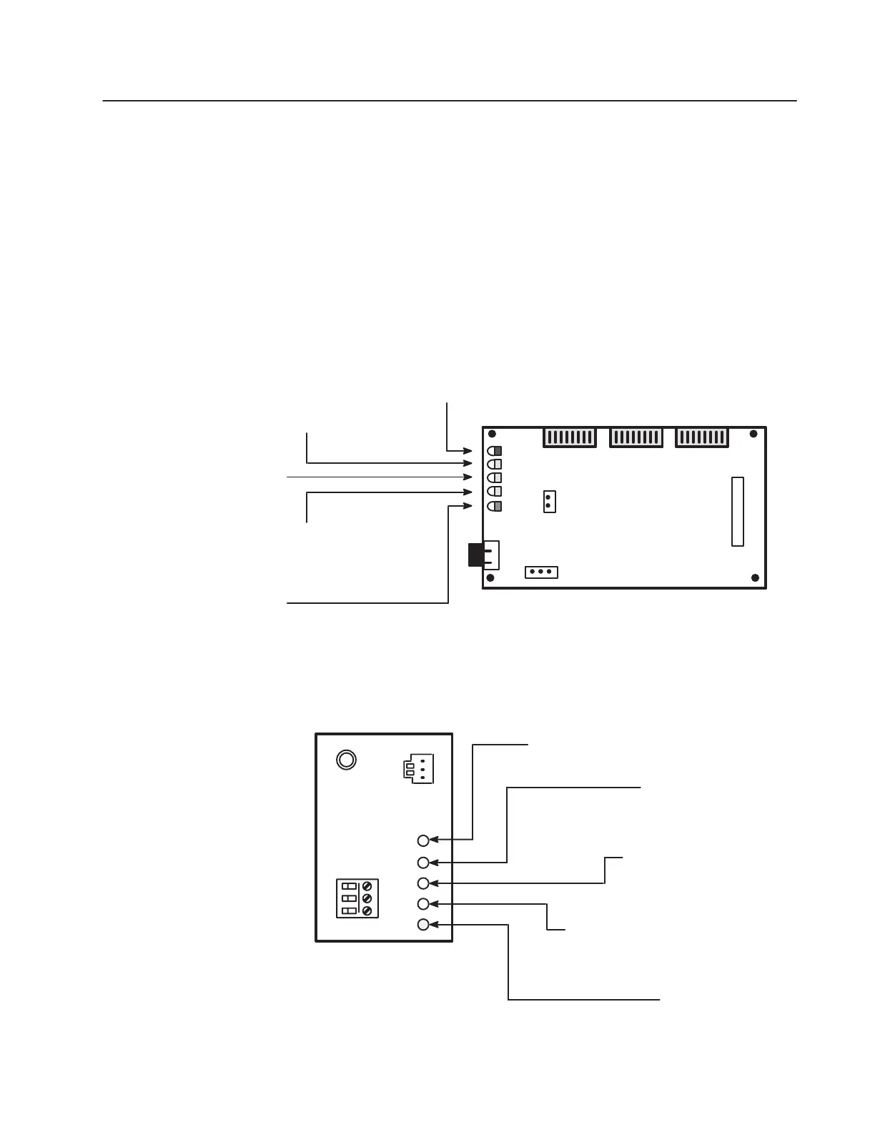
Chapter 4 provides information to help you troubleshoot your remote
I/O system using the LED indicators on the front of the device
(Figure 4.1). The remote I/O module is a non-serviceable device that
should be returned to Allen-Bradley for replacement when a major
fault exists that is attributable to the remote I/O communications
module itself.
Figure 4.1
LED Locations
SW1
Front View
Open Version
SW2SW3
Adapter Fault Status
(Red)
SCANport Status
(Green)
Adapter Health
(Green)
Remote I/O
Status (Green)
Remote I/O
Active (Green)
J4
Front View
Enclosed Version
..
.
Remote I/O
Status (Green)
Remote I/O
Active (Green)
Adapter Fault
Status (Red)
SCANport Status
(Green)
Adapter Health
(Green)
Refer to Table 4.A for details on LED operation.
J3
J2
J1
Chapter Objectives

 Loading...