4-2 Busbar Splice Kits
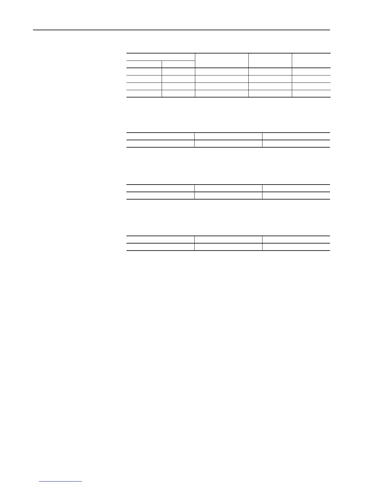
Table 4.B DC Power Bus Splice Kits
Table 4.C Special Power Bus Splice Kits
Use these kits when splicing directly to a Common AC Bus F-frame 2362
Unit or any G-frame 2362 Unit
.
Control Bus Splice Kit Catalog Numbers
Table 4.D Control Bus Splice Kits
PE/TE Bus Splice Kit Catalog Numbers
Table 4.E PE/TE Bus Splice Kits
Compatible with Frame Sizes
Continuous Power Bus
Rating (Amps) Straight Splice Kit Offset Splice Kit1336 PowerFlex
A, B, C, D, E, F 0 - 9 800 2300H-SKD-L08 2300H-SKD-Z08
A, B, C, D, E, F 0 - 9 1600 2300H-SKD-L16 2300H-SKD-Z16
A, B, C, D, E, F 0 - 9 3000 2300H-SKD-L30 2300H-SKD-Z30
G, H Up to 3000 2300H-SKD-L30S 2300H-SKD-Z30
Power Bus Rating (Amps) Straight Splice Kit Offset Splice Kit
600-3000 2300H-SKA-L30S 2300H-SKA-Z30
Compatible with Frame Sizes Straight Splice Kit Offset Splice Kit
All 2300H-SKC-L 2300H-SKC-Z
Compatible with Frame Sizes Power Bus Rating (Amps) PE/TE Bus Splice Kit
All 800-3000 2300H-SKG-30
 Loading...


