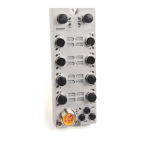
Do you have a question about the Allen-Bradley 1732ES-IB16 and is the answer not in the manual?
Summarizes warnings for explosion, personal injury, shock, burn, and arc flash hazards.
Defines the safe state and operational principles of the modules.
Covers configuration of safety inputs, outputs, test outputs, and delays.
Details the muting lamp feature and its monitoring for fault detection.
Covers enclosure, mounting, spacing, and grounding requirements for module installation.
Provides critical safety precautions for wiring, power supply, and module connections.
Details how to make electrical connections for 1791ES and 1732ES modules.
Guides on setting IP address, adding modules, configuring properties, inputs, and outputs.
Explains how to configure safety connection parameters like RPI and CRTL.
Covers saving, downloading module configurations, and managing ownership.
Details steps for resetting modules and replacing them in a GuardLogix system.
Explains how to set the Safety Network Number (SNN) for proper module identification.
Provides visual depictions and descriptions of module status indicators for diagnostics.
Details using Explicit Messaging to retrieve diagnostic status from 1791ES and 1732ES modules.
Summarizes I/O data support, assembly, and reference data for modules.
Lists calculated PFD, PFH, and MTTF values for safety assessment.
Details the parameter groups and settings for configuring safety inputs, outputs, and test outputs.
Covers technical specs (inputs, outputs, current) and environmental specs (temp, humidity, immunity).
Lists module certifications, directives, and compliance standards for different regions.
| Input Channels | 16 |
|---|---|
| Input Voltage | 24V DC |
| Communication Protocol | EtherNet/IP |
| IP Rating | IP67 |
| Input Voltage Range | 10-30V DC |
| Operating Temperature | -20 to 60 °C |
| Isolation | 50V continuous |
| Weight | 0.2 kg (0.44 lb) |


