14 POINT I/O 2 Current and 2 Voltage Input Analog Modules
Publication 1734-IN027C-EN-E - October 2016
Communicate with the Module
POINT I/O modules send (produce) and receive (consume) I/O data (messages). You
map this data into the processor’s memory.
The 1734-IE2C and 1734-IE2V modules produce 6 bytes of input data (scanner Rx) and
fault status data. The modules do not consume I/O data (scanner Tx).
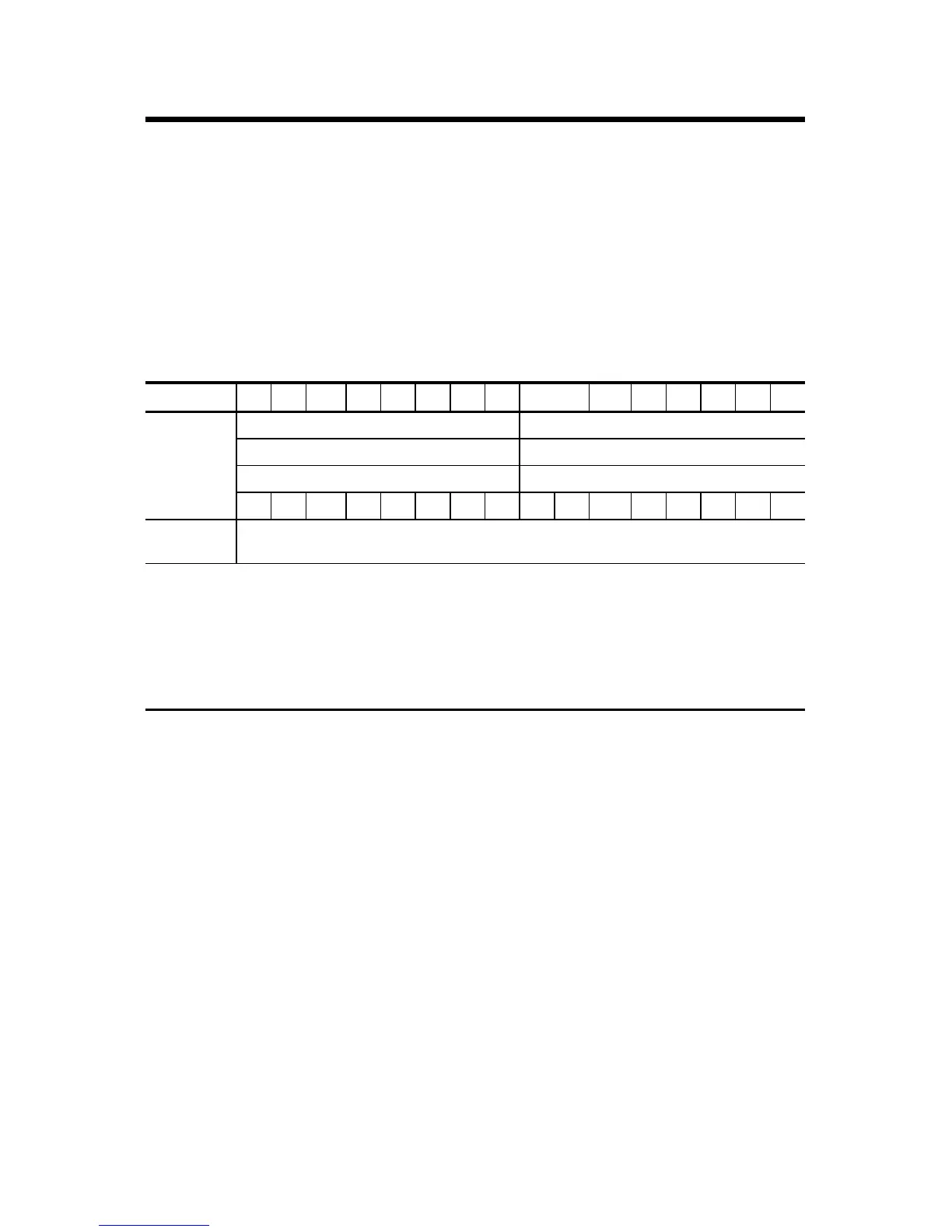
Default Data Map for 1734-IE2C and 1734-IE2V
Message size: 6 Bytes
15 14 13 12 11 10 09 08 07 06 05 04 03 02 01 00
Produces
(scanner Rx)
Input channel 0 – high byte Input channel 0 – low byte
Input channel 1 – high byte Input channel 1 – low byte
Status byte for channel 1 Status byte for channel 0
OR UR HHA LLA HA LA CM CF OR UR HHA LLA HA LA CM CF
Consumes
(scanner Tx)
No consumed data
Where: OR = Overrange; 0 = No error, 1 = Fault
UR = Underrange; 0 = No error, 1 = Fault
HHA = High/High Alarm; 0 = No error, 1 = Fault
LLA = Low/Low Alarm; 0 = No error, 1 = Fault
HA = High Alarm; 0 = No error, 1 = Fault
LA = Low Alarm; 0 = No error, 1 = Fault
CM = Calibration Mode; 0 = Normal, 1 = Calibration mode
CF = Channel Fault Status; 0 = No error, 1 = Fault

 Loading...


