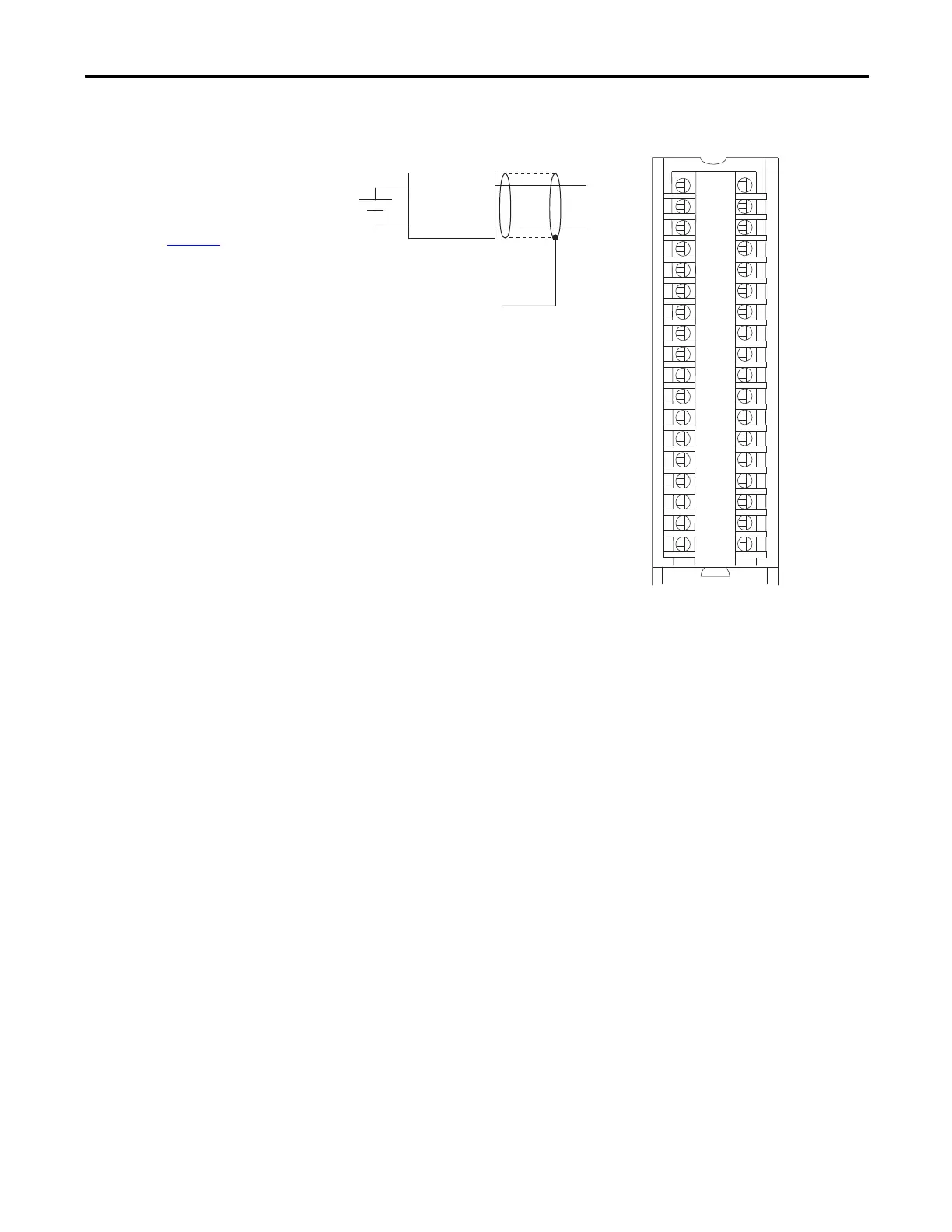
IN_0/V
IN_0/I/SRC
RTN-0
Not used
IN_2/V
IN_2/I/SRC
RTN_2
Not used
User Analog
Input Device
Shield Ground
IMPORTANT: If separate power sources
are used, do not exceed the specific
isolation voltage. For more information
on module specifications, see the 1756
ControlLogix I/O Specifications Technical
Data, publication 1756-TD002.
IN_4/V
IN_4/I/SRC
RTN-4
Not used
IN_6/V
IN_6/I/SRC
RTN_6
Not used
Not used
Not used
IN_1/V
IN_1/I/SRC
RTN-1
Not used
IN_3/V
IN_3/I/SRC
RTN_3
Not used
IN_5/V
IN_5/I/SRC
RTN-5
Not used
IN_7/V
IN_7/I/SRC
RTN_7
Not used
Not used
Not used
Device
External
Power
 Loading...


