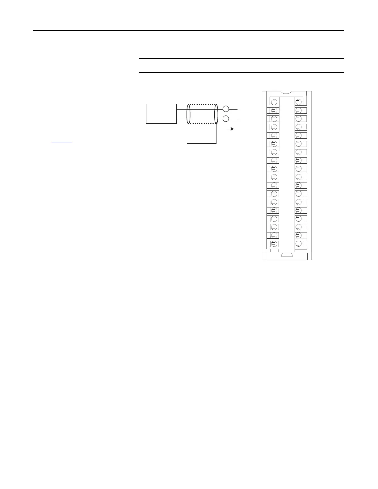
IN_0/V
IN_0/I/SRC
RTN-0
Not used
IN_2/V
IN_2/I/SRC
RTN_2
Not used
Shield Ground
IN_4/V
IN_4/I/SRC
RTN-4
Not used
IN_6/V
IN_6/I/SRC
RTN_6
Not used
Not used
Not used
IN_1/V
IN_1/I/SRC
RTN-1
Not used
IN_3/V
IN_3/I/SRC
RTN_3
Not used
IN_5/V
IN_5/I/SRC
RTN-5
Not used
IN_7/V
IN_7/I/SRC
RTN_7
Not used
Not used
Not used
IMPORTANT: Remember the following:
• If separate power sources are used, do
not exceed the specific isolation
voltage. For more information on
module specifications, see the 1756
ControlLogix I/O Specifications
Technical Data, publication
1756-TD002
.
• Place additional loop devices, for
example, strip chart recorders, at either
‘A’ location in the current loop.
2-wire
Transmi tter
 Loading...


