Rockwell Automation Publication 1756-UM540E-EN-P - December 2017 55
1756-IF8I Isolated Analog Input Module Chapter 3
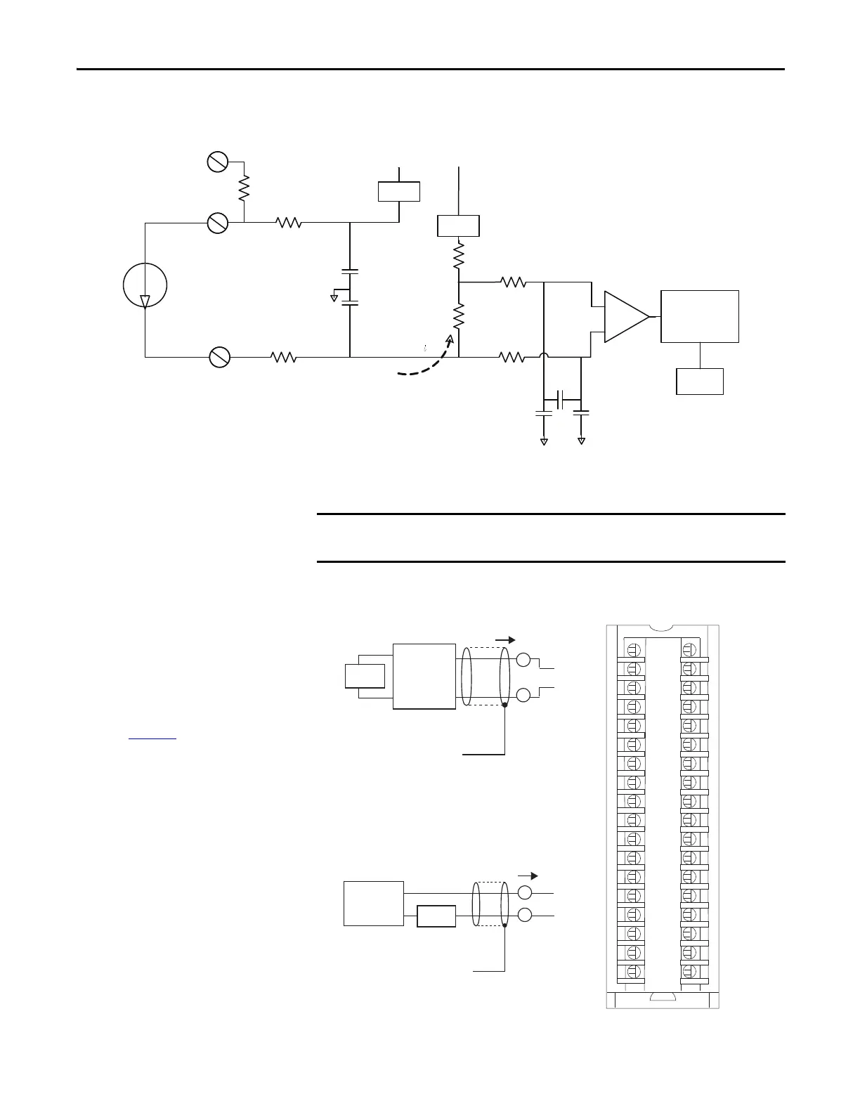
Figure 8 - 1756-IF8I Module Field-side Circuit with the Module Sourcing the Current Input Loop
Figure 9 - 1756-IF8I Module Wiring Diagram -Current Mode with External Loop Power
RTN-x
0.1 µF
IN_x/V
A/D Converter
7500 Ω
IN_x/I/SRC
1000 Ω
55 Ω
4…20 mA
Transmitter
0.01 µF0.01 µF
1000 Ω
20 Ω
0.01 µF
0.01 µF
Current Limit
24.9 Ω
25 Ω
Current Limit
i_sense
2.5V Vref
PGA
+18V
-18V
+
–
In this wiring diagram, an external, user-provided power supply provides
24V DC loop power.
+
–
A
A
i
A
A
i
1
3
5
7
019
1112
4131
6151
8171
0291
2212
4232
6252
8272
0392
2313
33
6353
2
34
8
6
4
+
–
IN_0/V
IN_0/I/SRC
RTN_0
Not used
IN_2/V
IN_2/I/SRC
RTN_2
Not used
4-wire
Trans mitter
Shield Ground
IN_4/V
IN_4/I/SRC
RTN_4
Not used
IN_6/V
IN_6/I/SRC
RTN_6
Not used
Not used
Not used
IN_1/V
IN_1/I/SRC
RTN_1
Not used
IN_3/V
IN_3/I/SRC
RTN_3
Not used
IN_5/V
IN_5/I/SRC
RTN_5
Not used
IN_7/V
IN_7/I/SRC
RTN_7
Not used
Not used
Not used
24V DC
IMPORTANT: Remember the following:
• If separate power sources are used, do
not exceed the specific isolation
voltage. For more information on
module specifications, see the 1756
ControlLogix I/O Specifications
Technical Data, publication
1756-TD002
.
• Place additional loop devices, for
example, strip chart recorders, at either
‘A’ location in the current loop.
24V DC
2-wire
Trans mit ter
Shield Ground
+
–
+
–
 Loading...


