CJC 0
IN_0(-)/B
IN_0/RTD C
IN_1(-)/B
IN_1/RTD C
IN_2(-)/B
IN_2/RTD C
IN_3(-)/B
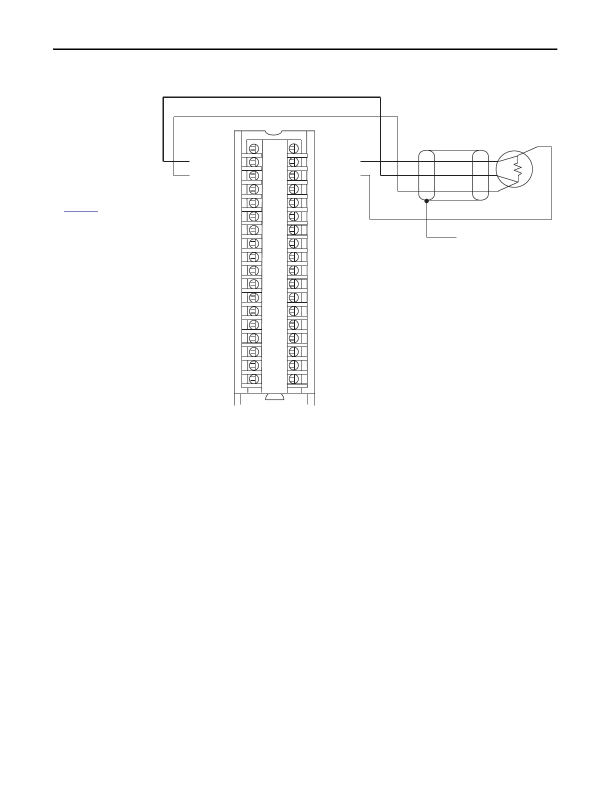
IMPORTANT: Remember the
following:
• If separate power sources
are used, do not exceed the
specific isolation voltage.
For more information on
module specifications, see
the 1756 ControlLogix I/O
Specifications Technical
Data, publication
1756-TD002
.
• Terminals 1, 2, 35, and 36
are not used in RTD
applications.
IN_3/RTD C
IN_4(-)/B
IN_4/RTD C
IN_5(-)/B
IN_5/RTD C
IN_6(-)/B
IN_6/RTD C
IN_7(-)/B
IN_7/RTD C
CJC 1
CJC 0
IN_0(+)/A
IN_0/RTD D
IN_1(+)/A
IN_1/RTD D
IN_2(+)/A
IN_2/RTD D
IN_3(+)/A
IN_3/RTD D
IN_4(+)/A
IN_4/RTD D
IN_5(+)/A
IN_5/RTD D
IN_6(+)/A
IN_6/RTD D
IN_7(+)/A
IN_7/RTD D
CJC1
Shield Ground
4-wire RTD
 Loading...


