CJC 0
IN_0(-)/B
IN_0/RTD C
IN_1(-)/B
IN_1/RTD C
IN_2(-)/B
IN_2/RTD C
IN_3(-)/B
IN_3/RTD C
IN_4(-)/B
IN_4/RTD C
IN_5(-)/B
IN_5/RTD C
IN_6(-)/B
IN_6/RTD C
IN_7(-)/B
IN_7/RTD C
CJC 1
CJC 0
IN_0(+)/A
IN_0/RTD D
IN_1(+)/A
IN_1/RTD D
IN_2(+)/A
IN_2/RTD D
IN_3(+)/A
IN_3/RTD D
IN_4(+)/A
IN_4/RTD D
IN_5(+)/A
IN_5/RTD D
IN_6(+)/A
IN_6/RTD D
IN_7(+)/A
IN_7/RTD D
CJC
Cold Junction Sensor
Cold Junction Sensor
+
–
+
–
mV Source
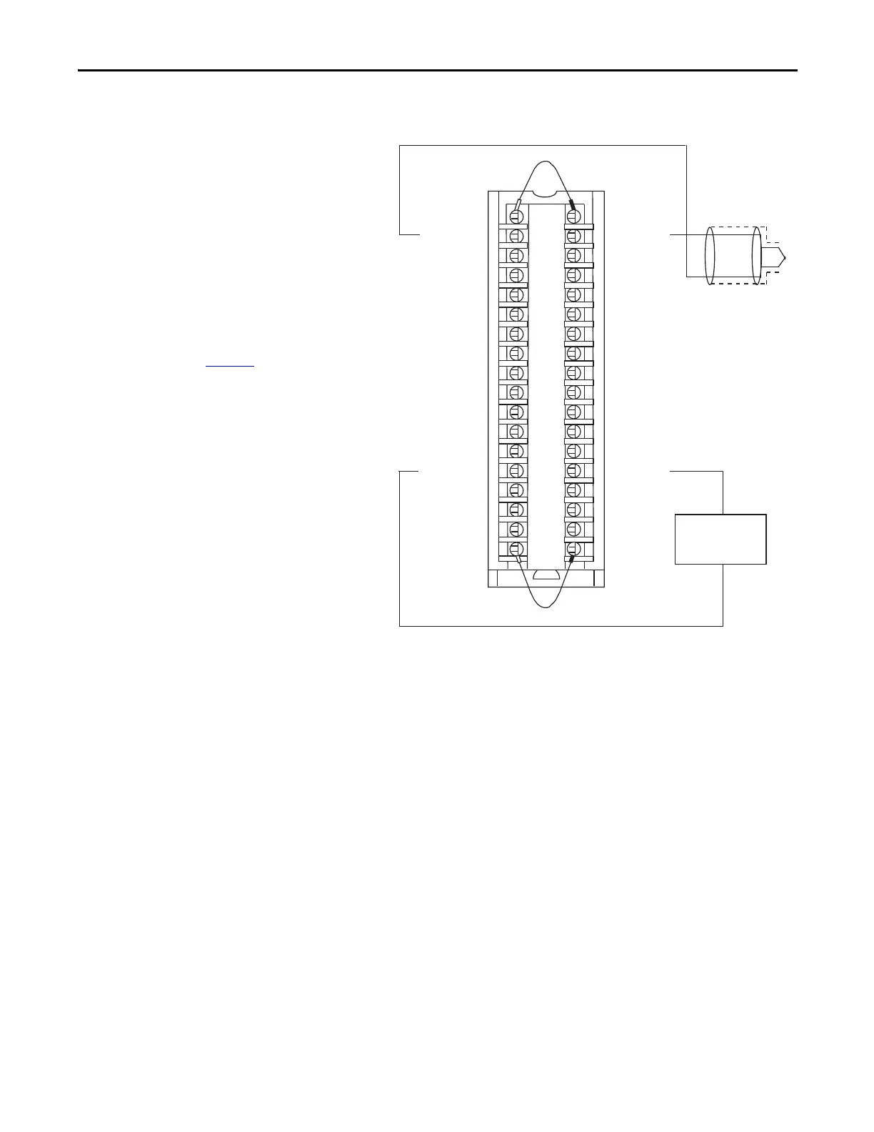
IMPORTANT: Remember the following:
• Connect the white end of the CJC sensor to the
even-numbered terminal., and connect the orange end of
the CJC sensor to the odd-numbered terminals.
For CJC 0:
– White end - Connected to terminal number 2
– Orange end - Connected to terminal number 1
For CJC 1:
– White end - Connected to terminal number 36
– Orange end - Connected to terminal number 35
• If separate power sources are used, do not exceed the
specific isolation voltage. For more information on module
specifications, see the 1756 ControlLogix I/O Specifications
Technical Data, publication 1756-TD002
.
 Loading...


