Rockwell Automation Publication 1756-UM540E-EN-P - December 2017 67
Temperature-sensing Analog Modules Chapter 4
You can latch process alarms. The alarm remains on, even if the condition causing
it to occur disappears, until the alarm is unlatched.
Alarm Deadband
You can configure an alarm deadband to work with these alarms. The deadband
lets the process alarm status bit remain set, despite the alarm condition
disappearing, as long as the input data remains within the deadband of the
process alarm. If the Alarm Deadband is mixed with Alarm Latching, an Unlatch
command while the Alarm is within the Deadband causes the Alarm to be
cleared.
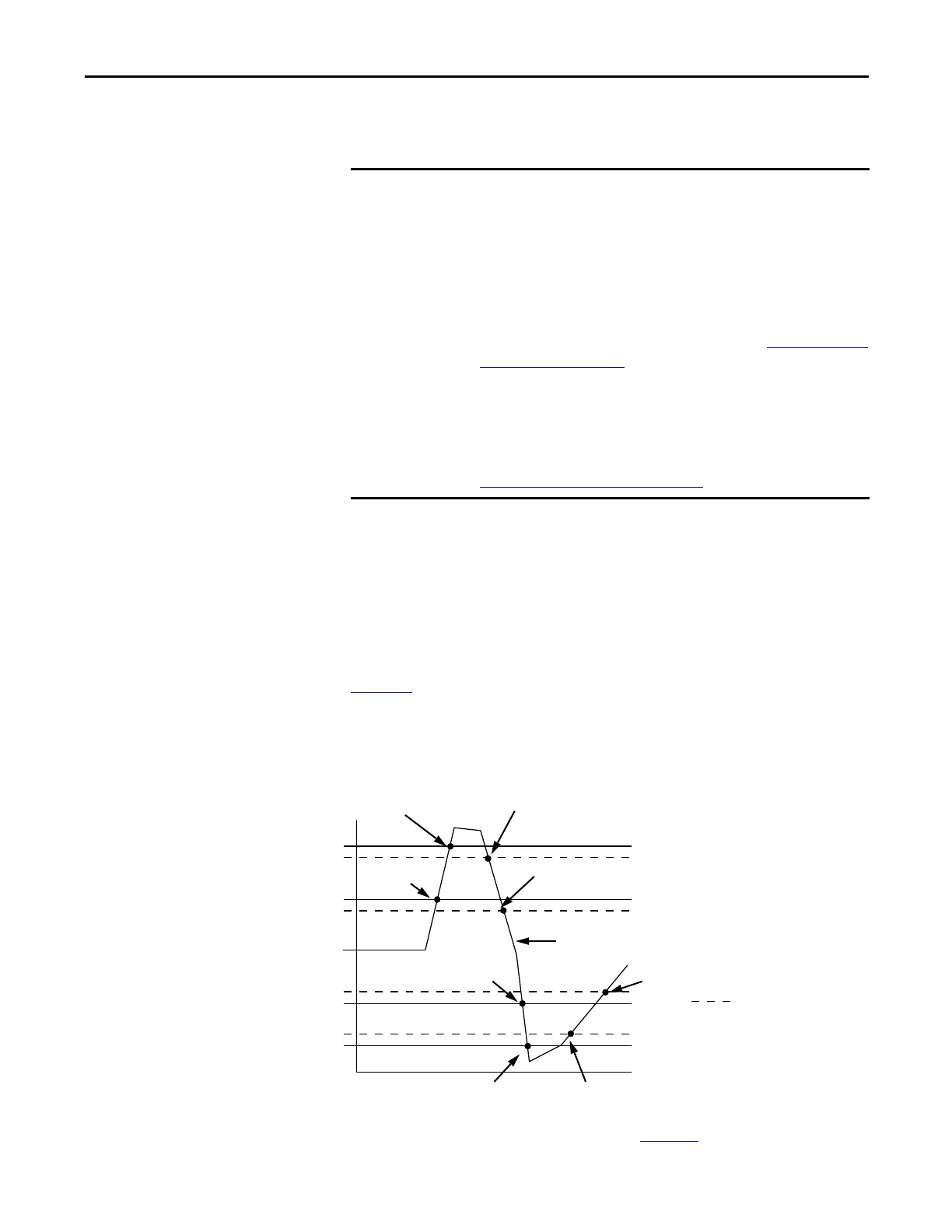
Figure 12
shows input data that sets each of the four alarms at some point during
module operation. In this example, latching is disabled; therefore, each alarm
turns Off when the condition that caused it to set ceases to exist.
Figure 12 - Alarm Deadband Alarm Settings
To see where to set the Alarm Deadband, see page 137.
You must manually unlatch the alarm. You can unlatch the alarm, by using one
of the following methods:
• While the project is online, click the Alarm Configuration tab on the
Module. Then click Unlatch to unlatch a specific alarm or Unlatch All to
unlatch all alarms.
• Change the module output tag for the alarm that you want to unlatch. For
example, the Ch[x].LLAlarmUnlatch tag to unlatch a Low Low Alarm.
For more information on module tags, see Appendix A, Analog I/O Module
Tag Definitions on page 181.
• Use a CIP Generic message.
For more information how to use a CIP Generic message, see Rockwell
Automation Knowledgebase article #63046, How to Reset Latched Status
of an Analog Module. You can access the article at:
https://rockwellautomation.custhelp.com/
43153
High high
Low low
Low
High
Alarm Deadbands
High high alarm turns Off.
High alarm remains On.
High high alarm turns On.
High alarm remains On.
Normal Input Range
Low low alarm turns Off.
Low alarm remains On.
High alarm turns Off.
Low low alarm turns On.
Low alarm remains On.
Low alarm turns Off.Low alarm turns On.
High alarm
turns On.
 Loading...

