Compact 1769-OF8C Analog Output Module 13
Publication 1769-IN065B-EN-P - September 2005
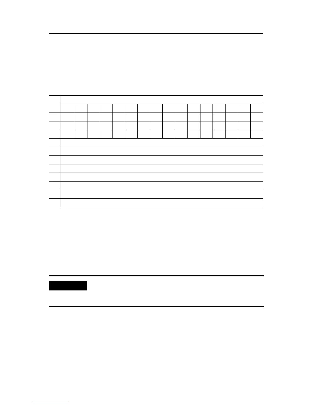
Input Data File
For each module, slot x, input data file words 3-10 contain the state of the module’s
output data (output data echo) file words 0-7. During normal operation, these input
words represent the analog values that the outputs are directed to by the control
program.
• PF = Analog power fail.
• S = General status (over-range, under-range, or open-circuit).
• D = Open-circuit diagnostics.
• H = Output held bit.
• U = Under-range (or low-clamp exceeded) alarm.
• O = Over-range (or high-clamp exceeded) alarm.
Word
Bit Position
15 14 13 12 11 10 9 8 7 6 5 4 3 2 1 0
0 PF S7 S6 S5 S4 S3 S2 S1 S0
1 D3 H3 U3 O3 D2 H2 U2 O2 D1 H1 U1 O1 D0 H0 U0 O0
2 D7 H7 U7 O7 D6 H6 U6 O6 D5 H5 U5 O5 D4 H4 U4 O4
3 Channel 0 Data Value
4 Channel 1 Data Value
5 Channel 2 Data Value
6 Channel 3 Data Value
7 Channel 4 Data Value
8 Channel 5 Data Value
9 Channel 6 Data Value
10 Channel 7 Data Value
IMPORTANT
The output module’s input data file reflects the analog output data
echo of the module, not necessarily the electrical state of the
output terminals. It does not reflect shorted or open outputs.

 Loading...


