Compact 1769-OF8C Analog Output Module 5
Publication 1769-IN065B-EN-P - September 2005
6. To allow communication between the controller and module, move the bus
lever fully to the left (4) until it clicks. Ensure it is locked firmly in place.
7. Attach an end cap terminator (5) to the last module in the system by using
the tongue-and-groove slots as before.
8. Lock the end cap bus terminator (6).
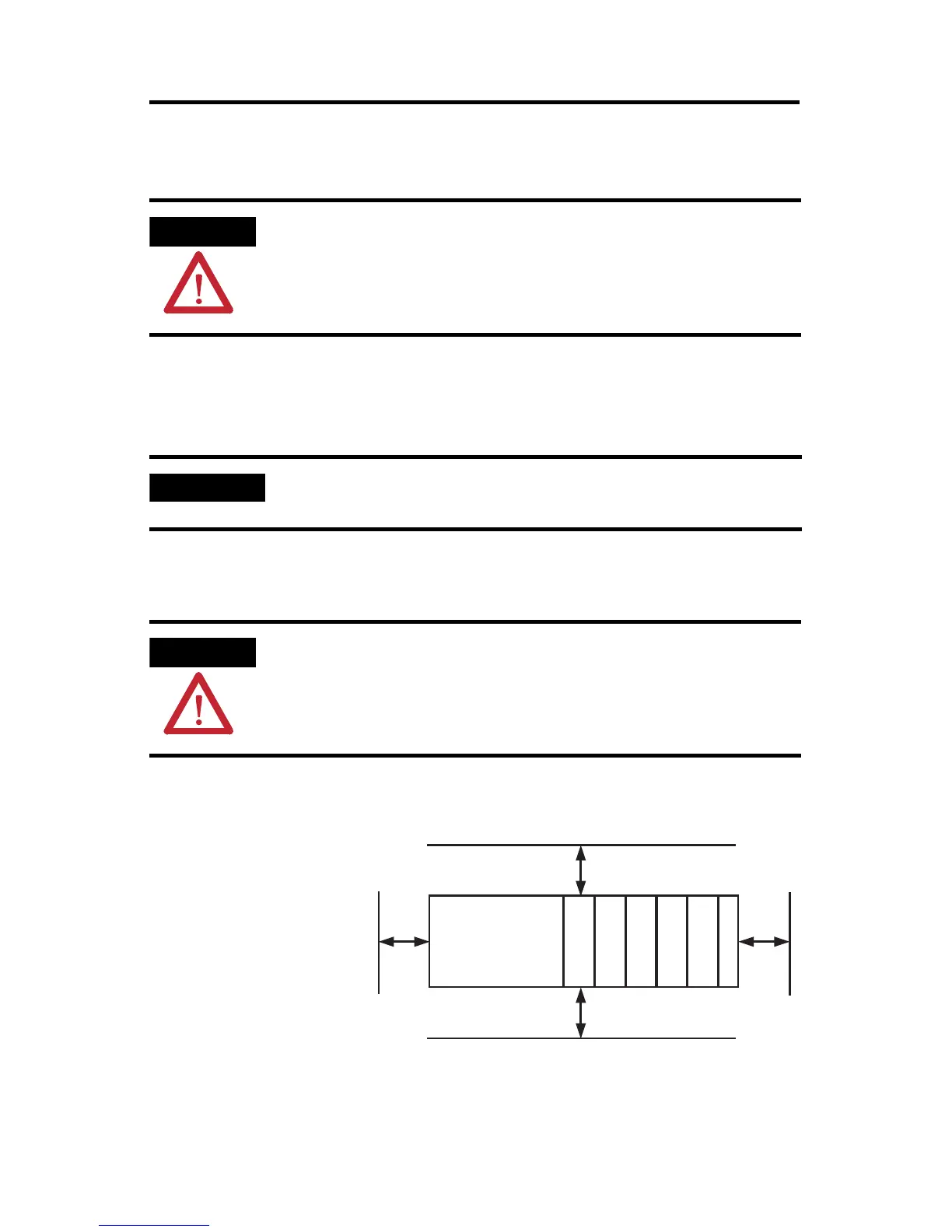
Mounting Expansion I/O
Minimum Spacing
Maintain spacing from
enclosure walls,
wireways, adjacent
equipment, etc. Allow 50
mm (2 in.) of space on all
sides for adequate
ventilation, as shown:
ATTENTION
When attaching I/O modules, it is very important that the bus
connectors are securely locked together to ensure proper
electrical connection.
IMPORTANT
A 1769-ECR or 1769-ECL right or left end cap must be used to
terminate the end of the serial communication bus.
ATTENTION
During panel or DIN rail mounting of all devices, be sure that all
debris (metal chips, wire strands, etc.) is kept from falling into the
module. Debris that falls into the module could cause damage on
power up.
Top
Bottom
Side Side
Host Controller
Compact I/O
Compact I/O
Compact I/O
Compact I/O
Compact I/O
End Cap
 Loading...


