Chapter 3
Addressing Modes for Your Remote I/O
3-13
Definition: The processor addresses one I/O module slot as one I/O group.
Concept: The physical address of each I/O group corresponds to an input
and output image table word. The type of module you install (8, 16, or
32-point) determines the number of bits in these words that are used.
You select 1-slot addressing by setting switches 5 and 6 of the I/O chassis
backplane switch assembly:
switch 5 to the ON position
switch 6 to the OFF position
With 1-slot addressing, because 16 input AND 16 output bits are available
in the processor’s image table for each I/O slot, you can use any mix of 8
or 16-point I/O modules in the I/O chassis.
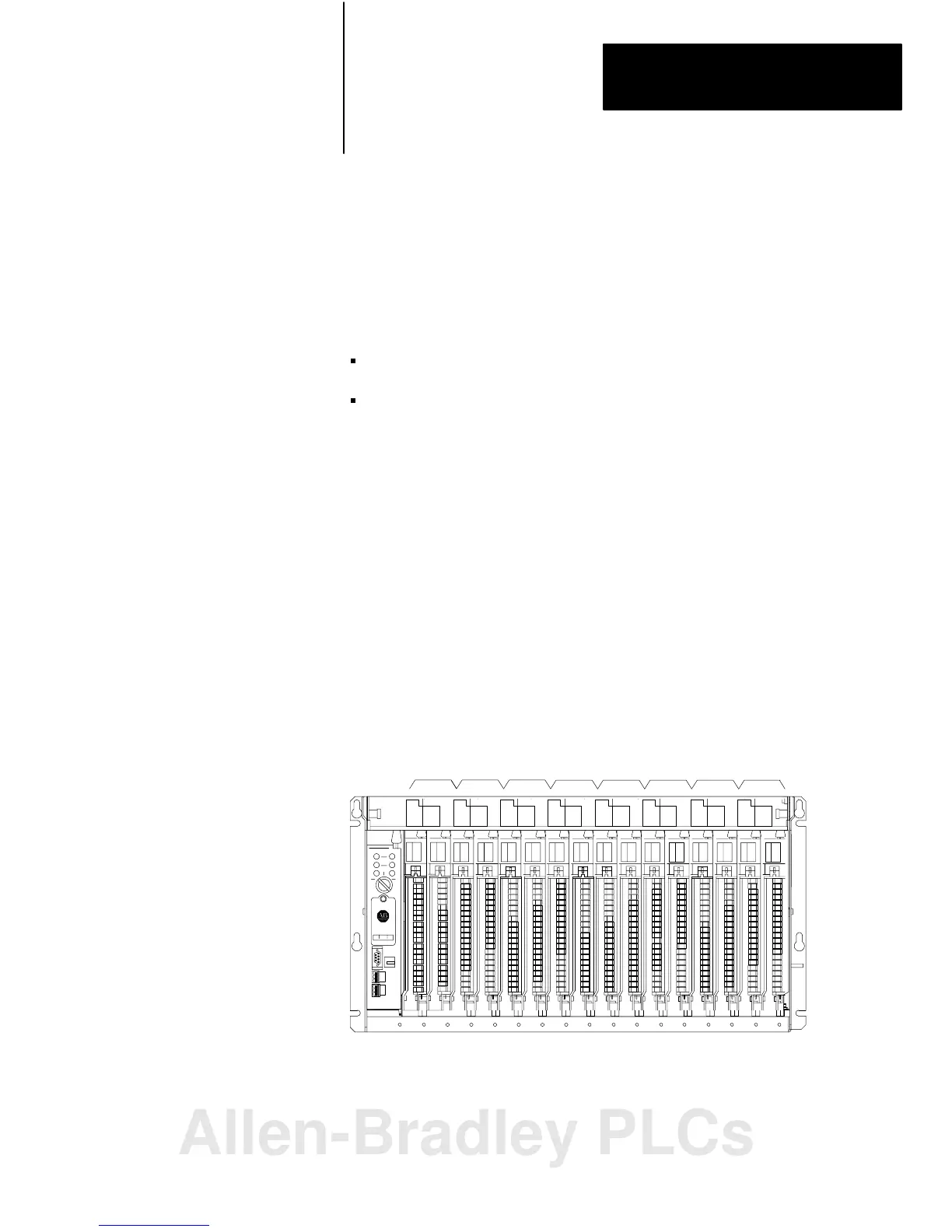
To use 32-point I/O modules with 1-slot addressing, you must install, as a
pair, an input module and an output module in 2 adjacent slots of the I/O
chassis beginning with I/O slot 0 (figure 3.8). If you cannot pair the
modules in this way, one of the two slots of the pair must be empty. For
example, if I/O slot 0 holds a 32-point input module, I/O slot 1 can hold an
8, 16, or 32-point output module (or a module that uses the backplane for
power only); otherwise, it must be empty.
Figure 3.11
Using
32point I/O Modules with 1slot Addressing
0123456789101112131415
I/O I/O I/O
I/O I/O
I/O
I/O I/O
Input/Output Pairs
I/O Chassis Slot Number
14973
1Slot Addressing
Allen-Bradley PLCs
 Loading...


