Addressing Modes for Your Remote I/O
Chapter 3
3-14
Thirty-two-point I/O modules need 32 input or 32 output bits in the
processor’s image table. Because only 16 input and 16 output bits are
available for each I/O group, to address a 32-point I/O module, the remote
I/O adapter module uses the unused input or output word associated with
the adjacent I/O slot.
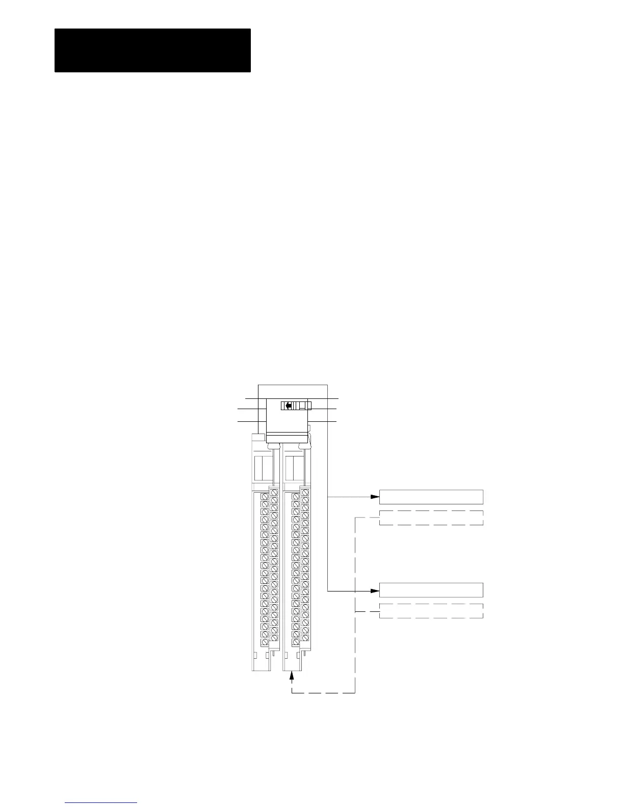
Refer to Figure 3.12. When the 1771-ASB remote adapter module
addresses a 1-slot I/O group containing a 32-point I/O module, the adapter
module uses the unused word assigned to the adjacent I/O module slot. For
example, the adapter module uses the unused input word associated with
I/O slot 1 (because that slot must hold an output module and does not use
its input word).
Figure 3.12 illustrates the concept of 1-slot addressing with two 32-point
I/O modules.
Figure 3.12
1slot
I/O Group Concept W
ith 32point I/O Modules
32-point I/O Modules
Input Word 0
Output Word 0
Image Table
W ords Allocated
for I/O Group 0
Input Word 1
Output Word 1
Image Table
W ords Allocated
for I/O Group 1
Slot 0
Input Module
I/O Group 0
Slot 1
Output Module
I/O Group 1
14258
 Loading...


