1–4
Overview of FLEX I/O and your Analog Modules
Publication
17946.5.2 - May 1996
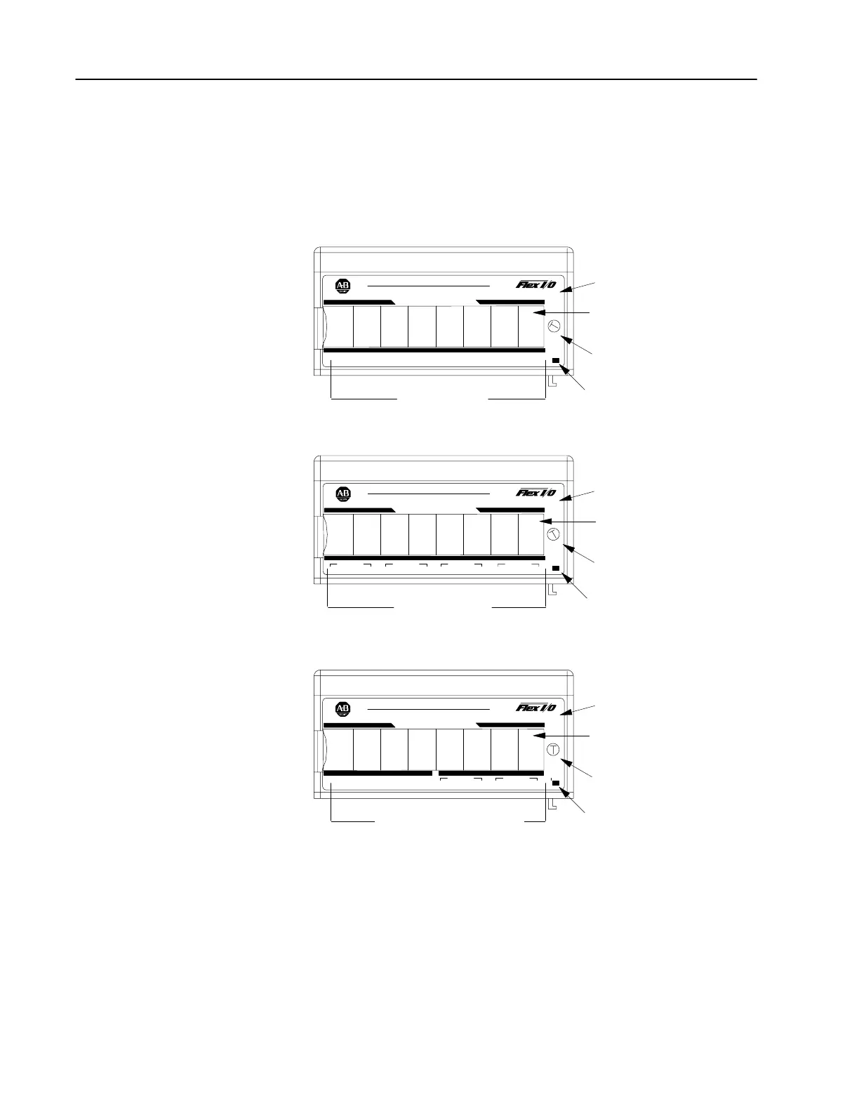
Each module has a unique label identifying its keyswitch position,
wiring and module type. A removable label provides space for
writing individual designations per your application.
INPUT
0
INPUT 2 INPUT 4 INPUT 6INPUT 1 INPUT 3 INPUT 5 INPUT 7
PWR
I
V
I
V
I
V
I
V
I
V
I
V
I
V
I
V
ANALOG INPUT
3
1794-IE8
AllenBradley
PWR
ANALOG OUTPUT
4
1794-OE4
AllenBradley
OUTPUT 0
I
RET RETV
OUTPUT 1
I
RET RETV
OUTPUT 2
I
RET RETV
OUTPUT 3
I
RET RETV
Removable
Label
Input Designators
Output Designators
Keyswitch
Position
Indicator (#3)
1794IE8
1794OE4
Keyswitch
Position
Indicator (#4)
Module Type
Module Type
INPUT
0
INPUT 2INPUT 1 INPUT 3
PWR
I
V
I
V
I
V
I
V V
ANALOG COMBO
5
1794-IE4XOE2
AllenBradley
Removable
Label
Module Type
OUTPUT
0
I
RET RETV
OUTPUT 1
I
RET RETV
Keyswitch
Position
Indicator (#5)
Green Power
Indicator
Green Power
Indicator
Input and Output Designators
1794IE4XOE2
Green Power
Indicator
Removable
Label
In this chapter you learned about the FLEX I/O system and the types
of analog modules and how they communicate with programmable
controllers.
Features of your Analog
Modules
Chapter Summary
 Loading...


