5–6
How Communication Takes Place and I/O Image Table Mapping with the DeviceNet Adapter
Publication
17946.5.2 - May 1996
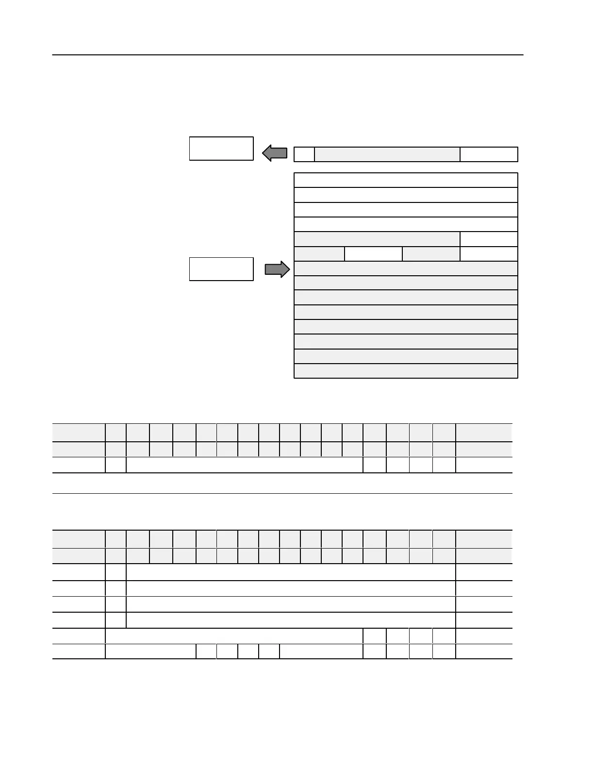
4 Output Analog Module (1794OE4 Series B) Image Table
Mapping
Module
Image
I/O Image
Analog Data Channel 0
Analog Data Channel 1
Analog Data Channel 2
Analog Data Channel 3
Not used
Not used
Not used
Not used
Not used
Not used Not used
Not used
Not used
Not used
Not used
Not used
Diagnostics
Config. Select
Full Range
Input Size
Output Size
0 or 1 Word
1 to 6 Words
Read
Write
OE
PU
Analog Output Module (1794-OE4/B) Read
Decimal Bit 15 14 13 12 11 10 09 08 07 06 05 04 03 02 01 00 Size
Octal Bit 17 16 15 14 13 12 11 10 07 06 05 04 03 02 01 00 Read Words
PU Not used - set to 0 W3 W2 W1 W0 Read Word 1
Where: PU
= Power up bit - included in series B modules only
.
W = Diagnostic bits for current output wire broken or load resistance high. (Not used on voltage outputs.)
Analog Output Module (1794-OE4/B) Write
Decimal Bit 15 14 13 12 11 10 09 08 07 06 05 04 03 02 01 00 Size
Octal Bit 17 16 15 14 13 12 11 10 07 06 05 04 03 02 01 00 Read Words
S Analog Data - Channel 0 Write Word 1
S Analog Data - Channel 1 Write Word 2
S Analog Data - Channel 2 Write Word 3
S Analog Data - Channel 3 Write Word 4
Not used - set to 0 OE3 OE2 OE1 OE0 Write Word 5
Not used - set to 0 C3 C2 C1 C0 Not used - set to 0 F3 F2 F1 F0 Write Word 6
 Loading...


