5–33
How Communication Takes Place and I/O Image Table Mapping with the DeviceNet Adapter
Publication
17946.5.2 - May 1996
FLEX I/O analog modules are supported by the DeviceNet adapter.
At present, these consist of:
Module Description Catalog Number: For image table mapping refer to:
8 Input Analog Module 1794IE8/B page 5-3
4 Output Analog Module 1794OE4/B page 5-6
4 in/2 out Analog Combo Module 1794IE4XOE2/B page 5-9
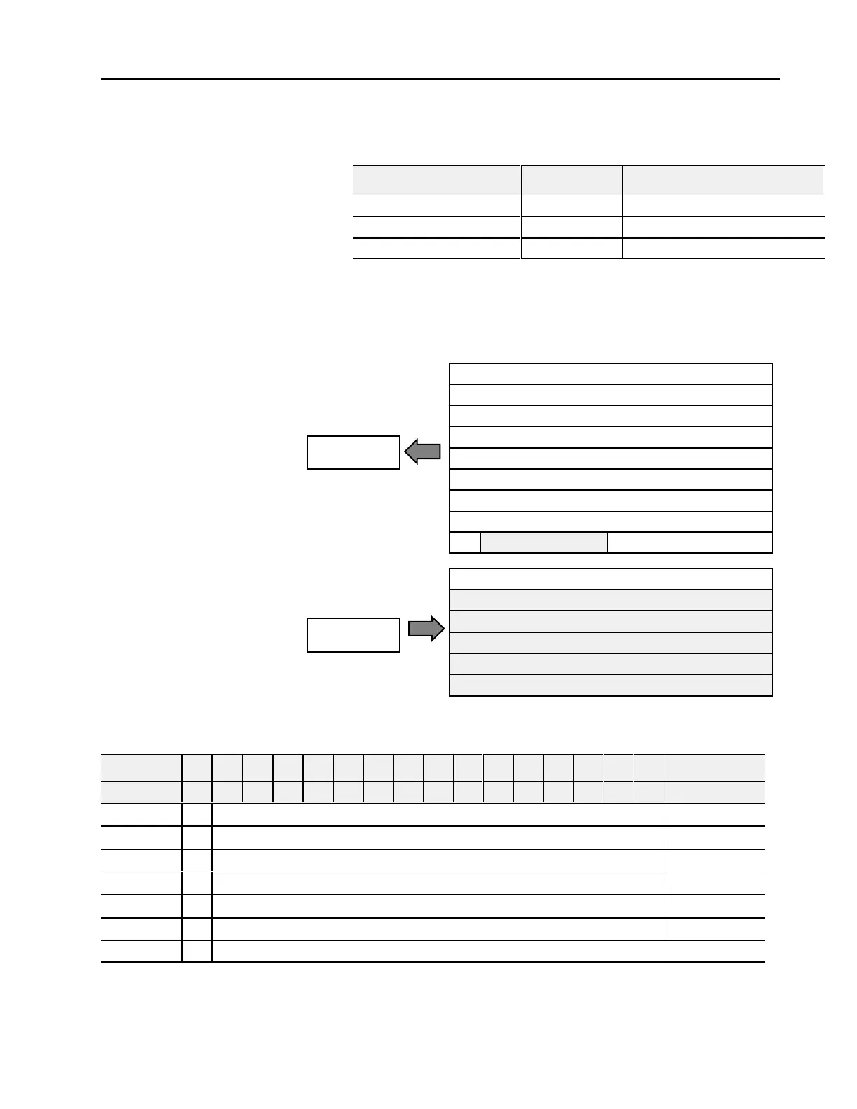
8 Input Analog Module (Cat. No. 1794IE8 Series B) Image Table
Mapping
Module
Image
I/O Image
Input Data Channel 0
Input Data Channel 1
Input Data Channel 2
Input Data Channel 3
Input Data Channel 4
Input Data Channel 5
Input Data Channel 6
Input Data Channel 7
Underrange
Configure select
Not used
Not used
Not used
Not used
Not used
Input Size
Output Size
0 or 1 Word
1 to 9 Words
PU
Analog Input Module (1794-IE8/B) Read
Decimal Bit 15 14 13 12 11 10 09 08 07 06 05 04 03 02 01 00 Size
Octal Bit 17 16 15 14 13 12 11 10 07 06 05 04 03 02 01 00 Read Words
S Analog Value Channel 0 Read Word 1
S Analog Value Channel 1 Read Word 2
S Analog Value Channel 2 Read Word 3
S Analog Value Channel 3 Read Word 4
S Analog Value Channel 4 Read Word 5
S Analog Value Channel 5 Read Word 6
S Analog Value Channel 6 Read Word 7
Mapping Data into the
Image Table
 Loading...


