2–4
How to Install Your Analog Module
Publication
17946.5.2 - May 1996
Installation of the analog module consists of:
•mounting the terminal base unit
•installing the analog module into the terminal base unit
•installing the connecting wiring to the terminal base unit
If you are installing your module into a terminal base unit that is
already installed, proceed to “Mounting the Analog Module on the
Terminal Base” on page 2–7.
Mounting the Terminal Base Unit on a DIN Rail
!
ATTENTION: Do not remove or replace a terminal
base unit when power is applied. Interruption of the
flexbus can result in unintended operation or machine
motion.
1.Remove the cover plug (if used) in the male connector of the unit
to which you are connecting this terminal base unit.
2.Check to make sure that the 16 pins in the male connector on the
adjacent device are straight and in line so that the mating female
connector on this terminal base unit will mate correctly.
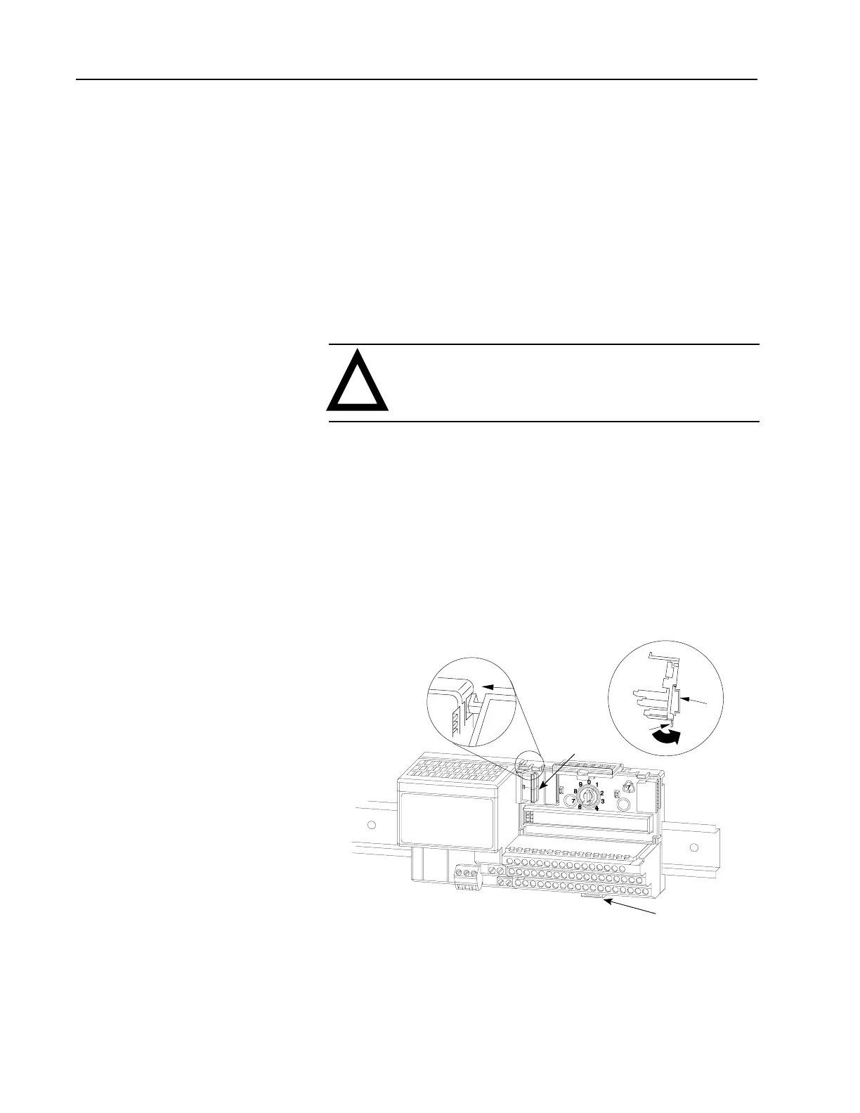
3.Position the terminal base on the 35 x 7.5mm DIN rail A (A-B pt.
no. 199-DR1; 46277-3; EN 50022) at a slight angle with hook B
on the left side of the terminal base hooked into the right side of
the unit on the left.
A
C
D
B
A
D
4.Make certain that the female flexbus connector C is fully
retracted into the base unit.
Installing the Module
 Loading...


