5–7
How Communication Takes Place and I/O Image Table Mapping with the DeviceNet Adapter
Publication
17946.5.2 - May 1996
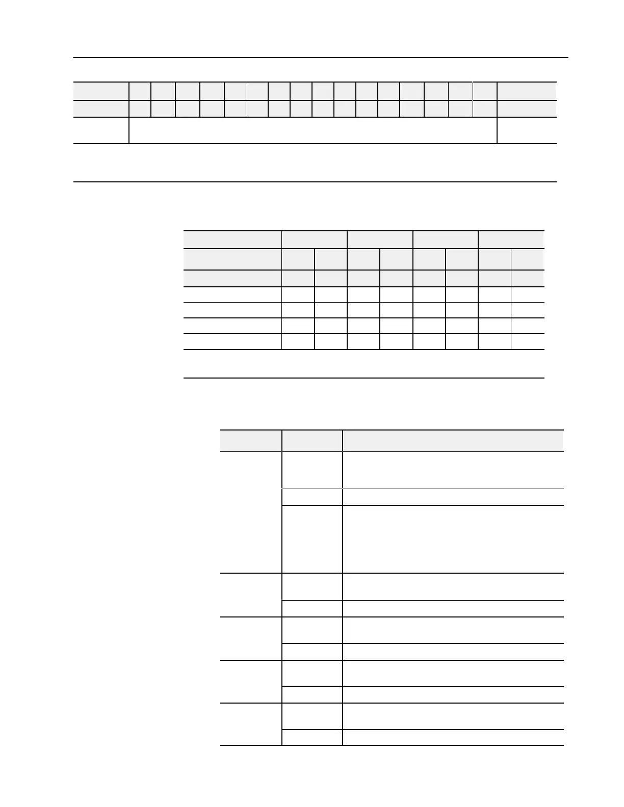
Size00010203040506070809101112131415Decimal Bit
Read Words00010203040506071011121314151617Octal Bit
Not used - set to 0
Write Words 7
thru 14
Where: S
= Sign bit (in 2'
s complement)
OE = Output enable bits (bit 00 corresponds to output 0, bit 01 corresponds to output 1 and so on.
ATTENTION: These bits must be set to 1.
C = Configure select bit
F = Full range bit
Range Selection Bits for the 1794-OE4/B Analog Output Module
(Write Word 6)
Channel No. Channel 0 Channel 1 Channel 2 Channel 3
F0 C0 F1 C1 F2 C2 F3 C3
Decimal Bit 00 08 01 09 02 10 03 11
4-20mA 0 1 0 1 0 1 0 1
0-10V dc/0-20mA 1 0 1 0 1 0 1 0
10 to +10V dc 1 1 1 1 1 1 1 1
Off
1
0 0 0 0 0 0 0 0
C
= Configure select bit
F = Full range bit
1
When configured to of
f, individual channels will send 0V or 0mA on Series B modules; 2V or 4mA on Series A modules.
Word/Bit Descriptions for the 1794-OE4/B Analog Output
Module
Word Decimal Bit Definition
Bits 0003
Current outputs only - When set (1), the wire on the output is
broken or the load resistance is too high. Bit 00 corresponds to
channel 0, bit 01 corresponds to channel 2, and so on.
Bits 0414 Not used - set to 0.
Read
Word 1
Bit 15
Power Up bit - included in series B modules only. This bit
is always 0 in series A modules. This bit is set to 1 when
all bits in the configuration register (write word 6) are 0
(unconfigured state). The configuration register can be
cleared by either of the reset inputs, or by the user writing all
zeroes to it.
Write Word 1
Bits 00-14
Channel 0 analog data - 12bit left justified two's complement
number; unused lower bits are zero; 420mA uses all 16 bits.
Bits 15 Channel 0 analog data sign bit.
Write Word 2
Bits 00-14
Channel 1 analog data - 12bit left justified two's complement
number; unused lower bits are zero; 420mA uses all 16 bits.
Bits 15 Channel 1 analog data sign bit.
Write Word 3
Bits 00-14
Channel 2 analog data - 12bit left justified two's complement
number; unused lower bits are zero; 420mA uses all 16 bits.
Bits 15 Channel 2 analog data sign bit.
Write Word 4
Bits 00-14
Channel 3 analog data - 12bit left justified two's complement
number; unused lower bits are zero; 420mA uses all 16 bits.
Bits 15 Channel 3 analog data sign bit.
 Loading...


