24V dc
FLEX I/O 16 Source Output Module 3
Publication 1794-5.3 – July 1999
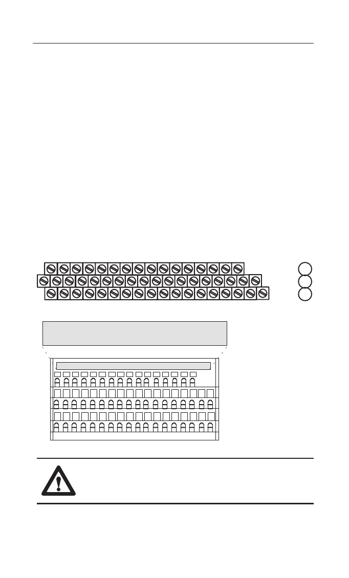
Wiring to a 1794-TB2, -TB3 or -TB3S Terminal Base Unit
1. Connect individual outputwiring to numbered terminals on the 0–15
row (A) as indicated in the table below.
1. Connect the associated output common to the corresponding terminal
on the 16–33 row (B) for each output as indicated in the table below.
(Commons are internally connected together.)
2. Connect +24V dc power to terminal 34 on the 34–51 row (C).
3. Connect dc return to terminal 16 on the 16–33 row (B).
4. If continuing power to the next terminal base unit, connect a jumper
from terminal 51 (+24V dc) on this base unit to terminal 34 on the
next base unit.
5. If continuing common to the next terminal base unit, connect a jumper
from terminal 33 (common) on this base unit to terminal 16 on the
next base unit.
17 18 19 20 21 22 23 24 25 26 27 28 29 30 31 32 33
0 1 2 3 4 5 6 7 8 9 10 11 12 13 14 15
16
1
345
7
91
11 1
13 14 15
35 36 37 38 39 40 41 42 43 44 45 46 47 48 49 50 51
34
1794-TB3
0 –15
34–51
16–33
A
B
C
0123456789101112131415
18 19 20 21 22 23 3324 25 26 27 28 29 30 31 3217
35 36 37 38 47 48 49 5034
51
16
Label placed at top of wiring area.
Row A
Row B
Row C
Row A
Row B
Row C
39 40 41 42 43 44 45 46
1794-TB3S
ATTENTION: Total current draw through the terminal
base unit is limited to 10A. Separate power connections to
the terminal base unit may be necessary.

 Loading...


