Publication 1794-6.5.8 - January 2010
Module Programming 37
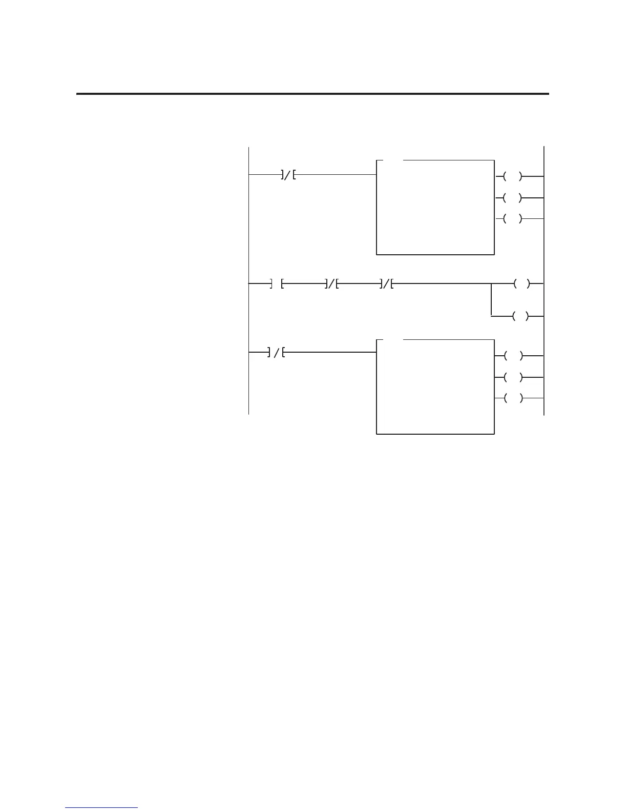
Figure 1.5
PLC-5 Family Sample Program Structure for the 1794-OF4I
BTR Enable Bit
EN
DN
BTW Enable Bit
1
3
ER
EN
DN
ER
BTR
BLOCK
TRANSFER READ
RACK:
GROUP:
MODULE:
DATA FILE:
LENGTH:
CONTINUOUS: N
BTW
BLOCK
TRANSFER WRITE
RACK:
GROUP:
MODULE:
LENGTH:
CONTINUOUS: N
2
0
0
N14:10
6
2
0
0
7
Program
Action
CONTROL:
N15:10
DATA FILE:
N14:50
CONTROL:
N15:0
N15:0
15
N15:10
15
Thereafter, the program continuously
performs read block transfers and write block
transfers.
At power-up in RUN mode, or when the
processor is switched from PROG to RUN,
the user program enables a block transfer
read.
2
14
N14:14
15
13
Power-up Bit
FP Bit
CF Bit
15
IC Bit
N14:14 N14:14 N14:56
Then it initiates a block transfer write to
configure the module and send data
values.
This rung toggles the Initate Configuration
bit from 0 to 1 to 0
L
14
N14:56
THIS BIT
MUST
BE 1
 Loading...


