FLEX I/O Isolated Output HART Analog Module 9
Publication 1794-IN120D-EN-P - September 2015
3. Connect the +V DC power lead to terminal 34 on the 34…51 row C, and the -V
common/return to terminal 16 on the 16…33 row B.
4. If daisy-chaining power to the next terminal base, connect a jumper from
terminal 51 (+V DC) on this base unit to terminal 34 on the next base unit.
5. If continuing DC common to the next base unit, connect a jumper from terminal
33 (common) on this base unit to terminal 16 on the next base unit.
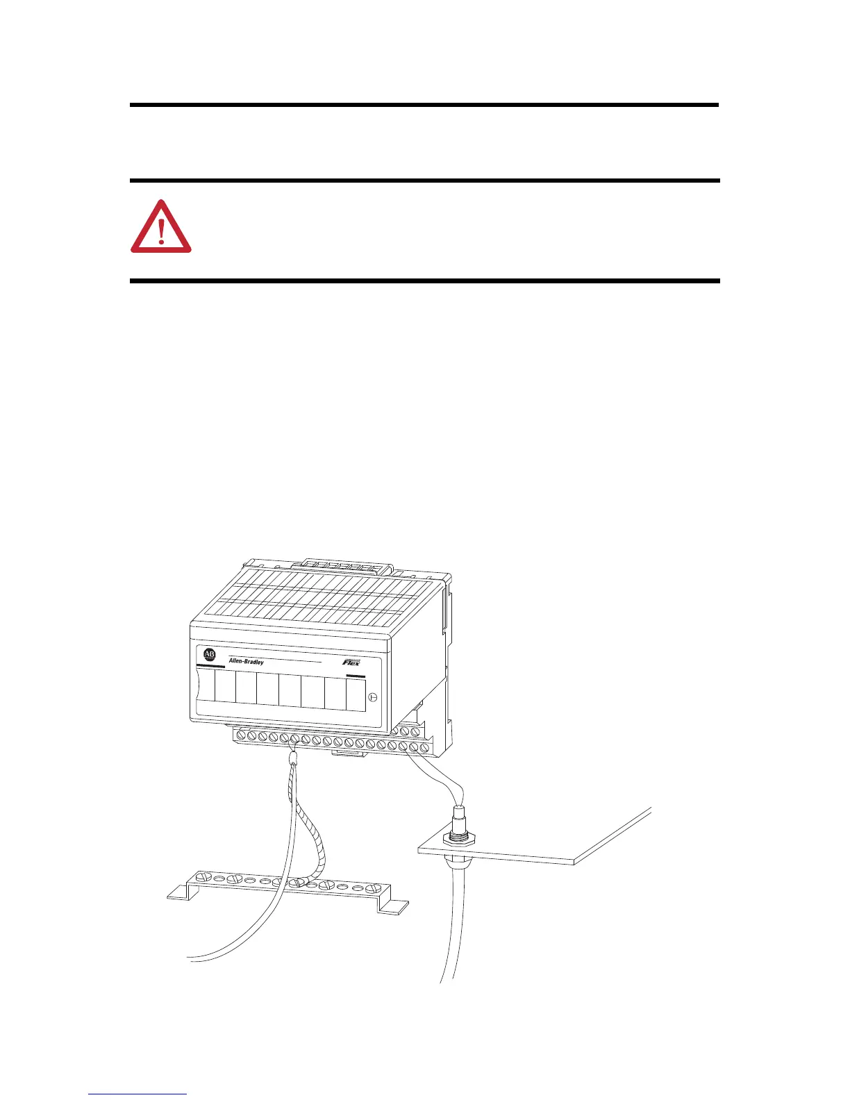
6. For both 1794-TB3 and 1794-TB3S bases, connect wiring shields to functional
earth ground as near as possible to the module.
Ground the Module
All I/O wiring must use shielded wire. Shields must be terminated external to the module,
such as bus bars and shield-terminating feed-throughs.
ATTENTION: To reduce susceptibility to noise, power analog modules and
digital modules from separate power supplies.
Do not exceed a length of 3 m (9.8 ft) for DC power cabling.
IN0 IN1 IN2 IN3
8 CH HART ISOLATED ANALOG INPUT
1794-xx8iH
I/O
IN4 IN5 IN6 IN7
PWR
3
 Loading...


