Rockwell Automation Publication IASIMP-QS024C-EN-P - August 2014 15
Chapter 1
Prepare the CompactLogix 5370 L1 Controller Hardware
This chapter describes how to install the hardware that is needed for your CompactLogix 5370 L1 control system.
What You Need
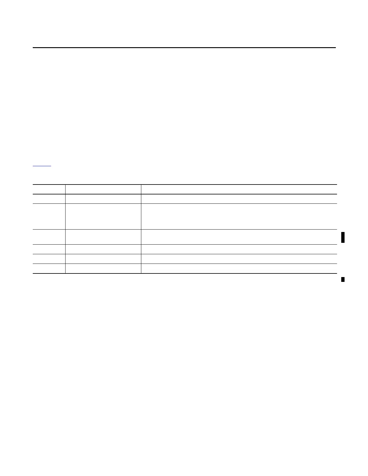
Tabl e 5 lists the hardware components that are used in this chapter.
Table 5 - Parts Used with This Quick Start
Quantity Cat. No. Description
1 or more N/A DIN rail (steel, not aluminum)
1 One of the following:
• 1769-L16ER-BB1B
• 1769-L18ER-BB1B
• 1769-L18ERM-BB1B
CompactLogix 5370 L1 controller
The tasks that are described in this publication use a 1769-L18ERM-BB1B controller.
1 User Selectable, for example 1606-
XLE120E
NEC Class 2/SELV switched-mode power supply
1 1734-OB4E POINT I/O 8-point 24V DC electronically fused output module
1 1783-EMS08T Stratix 6000 Ethernet managed switch
2
(1)
1585J-M8PBJM-2 RJ45-to-RJ45 patchcord Ethernet cables
(1) One Ethernet cable is required to connect the controller to the Ethernet switch and a second Ethernet cable is required to connect the Ethernet switch to the computer.

 Loading...


