Rockwell Automation Publication IASIMP-QS024C-EN-P - August 2014 21
Prepare the CompactLogix 5370 L1 Controller Hardware Chapter 1
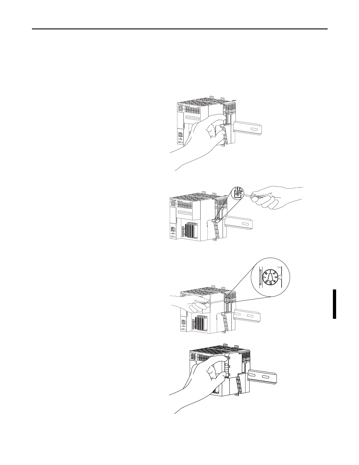
Install the Local Expansion Module
This quick start uses a 1734-OB4E POINT I/O output module in a local expansion module slot.
1. Make sure the DIN rail locking screw in the mounting base, for example, the 1734-TB mounting base, is in the
vertical position.
2. Align the tongue and groove slots of the
mounting base to the slots on the right side
of the controller and push it back until it
seats on the DIN rail.
3. Use a small-bladed screwdriver to rotate the
DIN rail locking screw to a horizontal
position, locking the mounting base in
place.
4. Set the key position on the mounting base
before installing the 1734-OB4E module.
This example shows position 1.
5. Make sure the output module’s key position
matches the position that is used on the
mounting base. Pull the key out from the
output module to reposition it if necessary.
6. Insert the module straight into the
mounting base and press to secure.

 Loading...


