Rockwell Automation Publication 1606-RM008A-EN-P - November 2021 35
DC-UPS - 24V, 20 A, 480 W Reference Manual
Back-Feeding Loads
Loads such as decelerating motors and inductors can feed voltage back to the
DC-UPS. This feature is also called return voltage immunity or resistance
against Back- E.M.F. (Electro Magnetic Force).
This DC-UPS is resistant and does not show malfunctioning when a load feeds
back voltage to the power supply. It does not matter whether the DC-UPS is on
or off.
The maximum allowed fed-back-voltage is 35V DC.
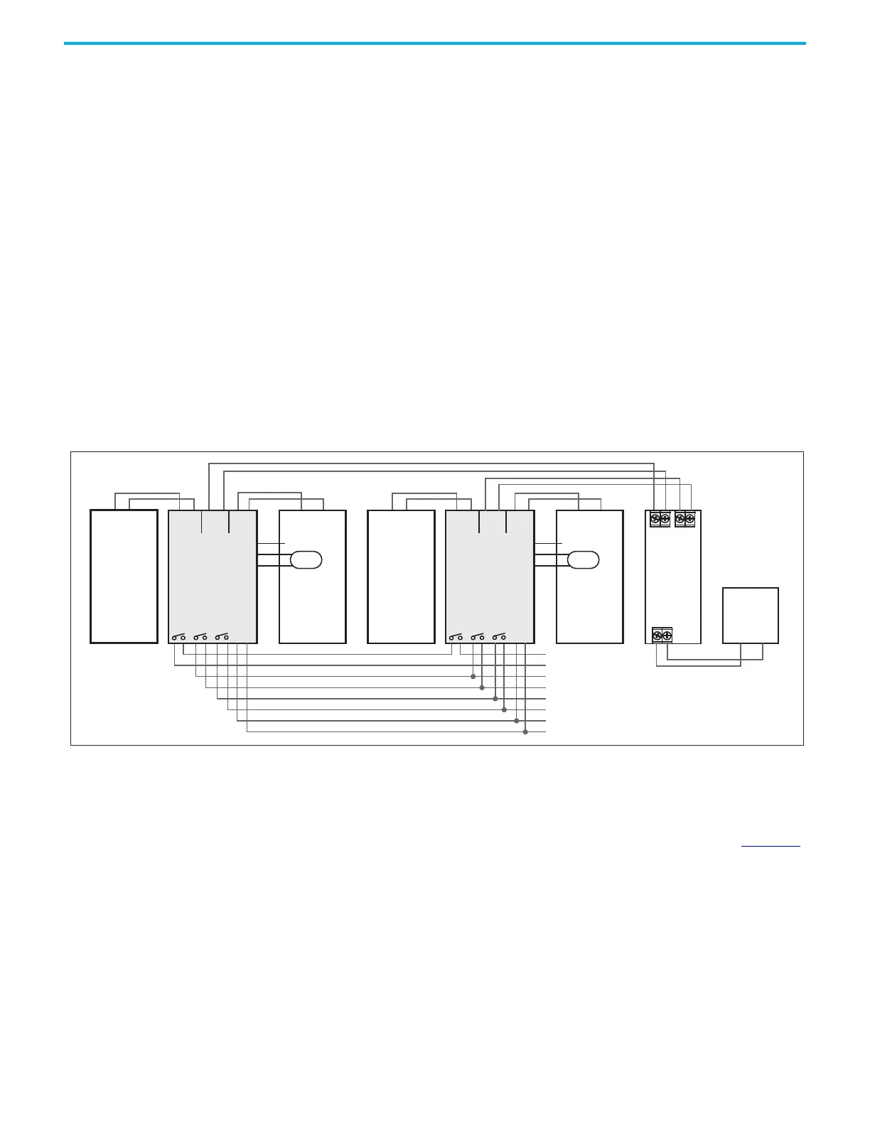
Parallel Use to Increase Output Current
Two DC-UPS units, two individual power supplies, two battery modules, and
one decoupling module can be used to build a system with higher output
current.
Figure 29 - Wiring Example for Parallel Use to Increase the Output Current
Parallel Use For Redundancy
Use the same schematic as for parallel use for higher output current Figure 29
and follow additional the following recommendations:
a. Use separate input fuses for each power supply.
b. Set the power supply into “Parallel use” mode if available.
c. Use a redundancy module to decouple the two power sources.
d. Monitor the individual sources. Therefore, use the alarm contacts of
the power supplies.
e. It is desirable to set the output voltages of all power supplies to the
same value (± 100 mV) or leave it at the factory setting.
+ +
- -
Power
Supply
DC 24V, 20A
Output
AC Input
L N PE
Load
+
-
+
-
OUT
+
-
IN 1
+
-
IN 2
Ready
Buffering
Inhibit
DC-UPS
IN OUT
++
-
-
Inhibit
+ -
Ready
Buffering
BAT
+
-
Replace
Battery
(13)
(12)
(11)
+
-
Battery
Module
Center-tap
Temp.
Sensor
DC-UPS
IN OUT
++
-
-
Inhibit
+ -
Ready
Buffering
BAT
+
-
Replace
Battery
(13)
(12)
(11)
+
-
Battery
Module
Center-tap
Temp.
Sensor
+ +
- -
Power
Supply
DC 24V, 20A
Output
AC Input
L N PE
Buffering
 Loading...