12 Rockwell Automation Publication 193-UM013B-EN-P - December 2019
Chapter 2 System Operation and Configuration
Figure 3 - Cat. No. 193-1EGJ Universal Protection Expansion Module Wiring
Cat. No. 193-1ERR Electronic Reset and Indication Display Module
The Cat. No. 193-1ERR Electronic Reset and Indication Display Module lets
you use the Cat. No. 193-ERID and 193-ERIDN Remote Indication and Display
module with your Advanced version (193/592-1EF) of the E100 relay.
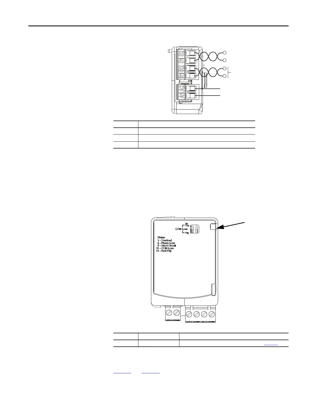
Figure 4 - Cat. No. 193-1ERR Electronic Reset and Indication Display Module
Wiring
Figure 3 and Figure 5 show the basic wiring for the 193-1ERR Module.
Note Number Information
1 Terminals R1 and R2 are used with 193-ERID and 193-1ERIDN modules.
2 External power must be user supplied. 24…240V, 47…63 Hz or DC.
3 Reserved for 193-CBCT external ground fault current sensor.
Note Number Feature Information
1 Accessory Diagnostic LED For more information about the diagnostic LED codes, see Chapter 3
.
R1
R2
S1
S2
A1
A2
Accessory Diagnostic LED
(1)

 Loading...


