Rockwell Automation Publication 193-UM013B-EN-P - December 2019 13
System Operation and Configuration Chapter 2
Figure 5 - Cat. No. 193-1ERR Electronic Reset and Indication Display Module Wiring
Cat. No. 193-ERID or 193-1ERIDN Remote Indication and Display
Module
The remote indication and display modules let you view the status of the
E100 relay from the front of a panel. Cat. No. 193-ERID also features a
reset button. The light-emitting diode (LED) status indicators notify you of the
status of the overload relay.
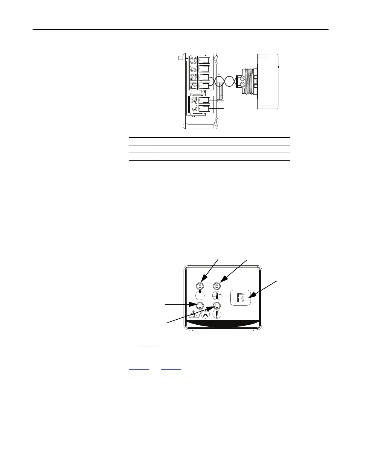
Figure 6 - Cat. No. 193-ERID and 193-1ERIDN Remote Indication and Display Module Features
See page 17 for information about the fault and status codes for the remote
indication and display modules.
Figure 3
and Figure 5 show the basic wiring for the 193-ERID and 193-1ERIDN
Modules.
Note Number Information
1 Cat. No. 193-ERID or 193-1ERIDN Remote Indication and Display module.
2 External power must be user supplied. 24…240V, 47…63 Hz or DC.
R2
R1
A1
A2
Reset (193-ERID only)
Module Power/Status
Fault Status
Phase Loss
Overload

 Loading...


