Rockwell Automation Publication 193-UM013B-EN-P - December 2019 19
Appendix A
Wiring Diagrams
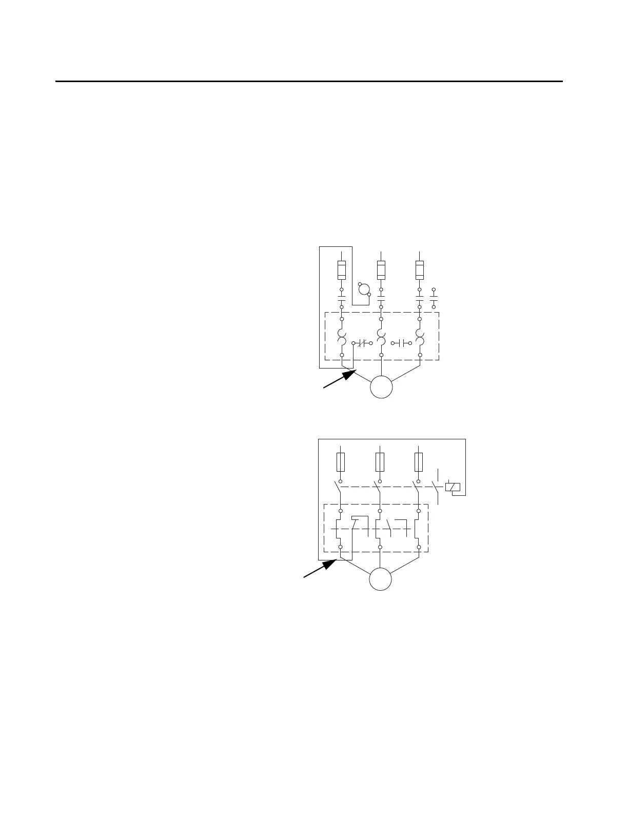
E100 Wiring Configurations
The following pages illustrate various wiring configurations for the E100™ Electronic
Overload Relay.
Figure 8 - 3-Phase, Full-voltage Direct-on-line Starter, NEMA Symbology
Figure 9 - 3-Phase, Full-voltage Direct-on-line Starter, IEC Symbology
95
L2 L3 13L1
14
A1
A2
T2 T3T1
96 97 98
T1 T3
T2
Connection must be
fitted by the user
Short-circuit
Protection Device
95
3
13
1
14
A1
A2
462
96
U
V
5
97 98
W
Connection must be
fitted by the user
Short-circuit
Protection Device

 Loading...


