20 Rockwell Automation Publication 193-UM013B-EN-P - December 2019
Appendix A Wiring Diagrams
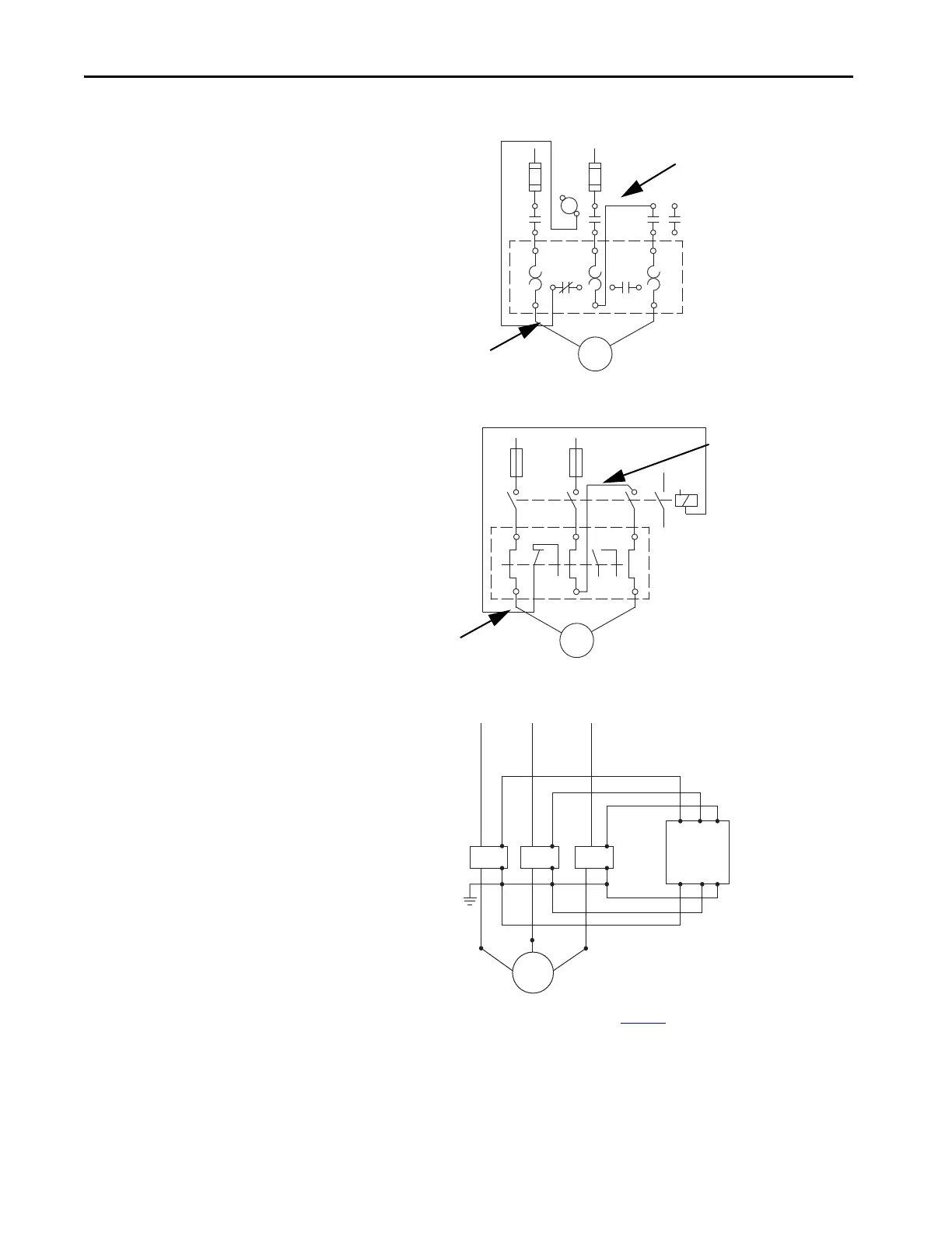
Figure 10 - 1-Phase, Full-voltage Direct-on-line Starter, NEMA Symbology
Figure 11 - 1-Phase, Full-voltage Direct-on-line Starter, IEC Symbology
Figure 12 - E100 Overload Relay with External Current Transformer
95
L2 L3 13L1
14
A1
A2
T2 T3T1
96 97 98
T1 T2
Connection must be
fitted by the user
Short-circuit
Protection Device
Connection must be
fitted by the user
95
35
13
1
14
A1
A2
462
96 97 98
U1 U2
Connection must be
fitted by the user
Short-circuit
Protection Device
Connection must be
fitted by the user
M
L1/1
L1/1
T1/2 T2/4 T3/6
L2/3 L3/5
L2/3 L3/5
H1(Dot) H1(Dot) H1(Dot)
H2 H2 H2
X1
X1 X1
X2X2X2
CT1
T1/2
T2/4
T3/6
CT2 CT3
Overload Relay
For more information about how to install an external Current Transformer, see Bulletin 193 Core Balanced Ground
Fault Sensor Application and Installation Instructions, publication 193-IN047
.

 Loading...


