16 Rockwell Automation Publication 193-UM013B-EN-P - December 2019
Chapter 3 Troubleshooting
Table 3 - 193-1EGJ and 193-1ERR Remote Indication and Display Module Fault/Status Codes
The status LED indicates the module status by flashing a red trip code. The
number of flashes followed by a pause identifies the specific trip code as shown in
Tab le 4
Table 4 - Trip Code Identification
Remote Indication Display
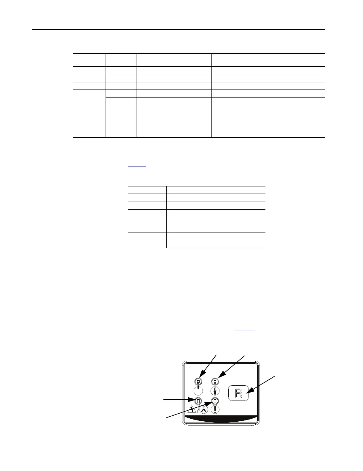
There are four LED status indicators on the front of the Cat. No. 193-ERID and
193-1ERIDN modules. These status indicators show Module Power/Status,
Overload, Phase Loss, and Fault Status. See Figure 7
Figure 7 - Cat. No. 193-ERID and 193-E1ERIDN Remote Indication and Display Module Features
Status Indicator
Color
Solid/Flashing Description Solution
Green
Flashing Module powered —
Solid Module powered and motor current present —
Amber Flashing Warning
Red
Flashing Fault detected and overload relay tripped
Solid
Hardware fault; internal hardware fault
detected and overload relay trip attempted
• Recover fault by cycling overload relay accessory supply voltage
• Verify that the supply voltage is within limits
• Verify the wiring to the terminals is correct
• Verify that the pins that connected the accessory to the overload
relay are not damaged or misaligned
• Verify the operating temperature of the devices is within
specification limits
No. of Flashes Trip Type
1Overload Trip
2Phase Loss
3 Ground Fault
5Jam
8Short Circuit
10 COM Loss
(1)
(1) If you experience repeated COM Loss trips, this may be due to a damaged communication
interface cable. To test whether this is the case, unplug the communication interface cable
from the communication port and wait at least 3 seconds before re-connecting. If the
issue persists, consider replacing the communication interface cable.
11 Test Trip
Reset (193-ERID only)
Module Power/Status
Fault Status
Phase Loss
Overload

 Loading...


