Publication 2198-PC002D-EN-P - November 2017
Supersedes Publication 2198-PC002C-EN-P - February 2016 Copyright © 2017 Rockwell Automation, Inc. All rights reserved. Printed in the U.S.A.
Allen-Bradley, Kinetix, MP-Series, and Rockwell Automation are trademarks of Rockwell Automation, Inc.
Trademarks not belonging to Rockwell Automation are property of their respective companies.
Rockwell Otomasyon Ticaret A.Ş., Kar Plaza İş Merkezi E Blok Kat:6 34752 İçerenköy, İstanbul, Tel: +90 (216) 5698400
Rockwell Automation maintains current product environmental information on its website at http://www.rockwellautomation.com/rockwellautomation/about-us/sustainability-ethics/product-environmental-compliance.page.
Wiring Requirements
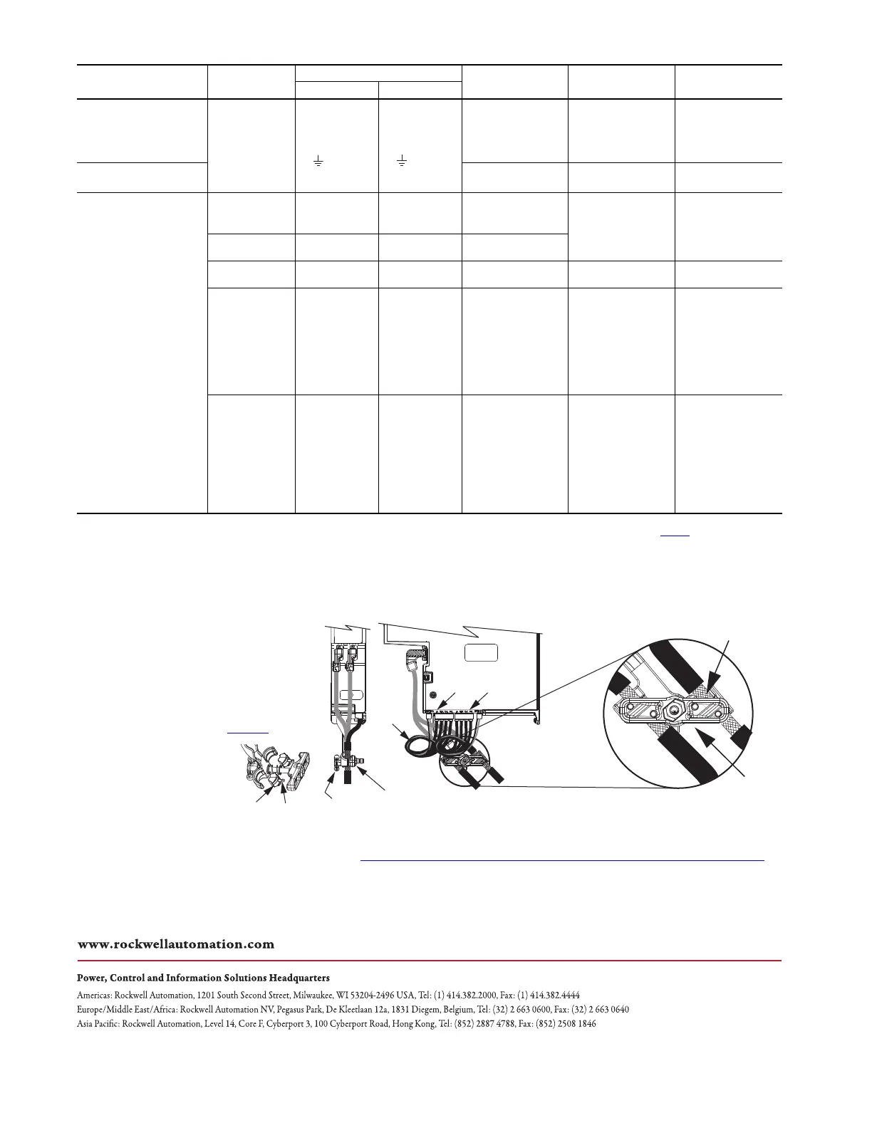
Shield Clamp Installation
Factory-supplied 2090-Series single motor cables are shielded and the braided cable shield must terminate at the drive during installation. The exposed area must be clamped (with the clamp provided) at the bottom front of the drive.
Clamp spacers, included with the dual-axis inverters and held captive by rivets, are not needed for Kinetix VP motor installations, and can be removed.
Dual-axis Inverter
Cat. No.
Description
Connects to Terminals
Wire Size
(1)
mm
2
(AWG)
(1) Wire size is expressed as a range where solid wire is at the low end of the range (smaller diameter) and stranded wire is at the high end (larger diameter). For example, 6 (solid)…25 (stranded) mm
2
or 10 (solid)…4 (stranded) AWG.
Strip Length
mm (in.)
Torque Value
N•m (lb•in)
Pin Signal
2198-D006-ERSx
2198-D012-ERSx
2198-D020-ERSx
2198-D032-ERSx
Motor power
(axis A and B)
Motor power cable depends on
motor/drive combination.
0.75…2.5
(2)
(18…14)
(2) Building your own cables or using third-party cables for Kinetix VP motors is not an option. Use 2090-CSxM1DE/DG single motor cables. Refer to the Kinetix Motion Accessories Specifications Technical Data, publication KNX-TD004, for cable specifications.
10.0 (0.39)
0.5…0.6
(4.4…5.3)
2198-D057-ERSx
2.5…6
(2)
(14…10)
10.0 (0.39)
0.5…0.8
(4.4…7.1)
2198-Dxxx-ERSx
PELV/SELV
24V power
(connector plug)
CP-1
CP-2
24V+
24V–
0.5…2.5
(20…14)
7.0 (0.28)
0.22…0.25
(1.9…2.2)
Brake power
(axis A and B)
BC-1
BC-2
MBRK+
MBRK–
N/A
(3)
(3) Motor brake wires are included (when specified) in the Bulletin 2090 motor cable.
DC Bus power Bus bar
DC–
DC+
N/A
(4)
(4) Shared DC-bus power connections are always made from one drive to another over the bus-bar connection system. These terminals do not receive discrete wires.
N/A
(4)
N/A
(4)
Safety
ST0-1
ST0-2, STO-10
ST0-3, STO-11
ST0-4, STO-12
ST0-5, STO-13
ST0-6, STO-14
ST0-7, STO-15
ST0-8, STO-16
ST0-9
SB+
S1A
SCA
S2A
SB-
S1B
SCB
S2B
N/C
0.14…1.5
(26…16)
10.0 (0.39)
N/A
(5)
(5) This connector uses spring tension to hold wires in place.
Digital inputs
IOD-1
IOD-2
IOD-3
IOD-4
IOD-5
IOD-6
IOD-7
IOD-8
IOD-9
IOD-10
IN1
COM
IN2
COM
SHLD
IN3
COM
IN4
COM
SHLD
0.14…1.5
(26…16)
10.0 (0.39)
N/A
(5)
D+
D-
D+
D-
MF-A MF-B
Motor Cable
Shield Clamp
2198-KITCON-DSL
Motor Feedback Connector Kits
(supplied with 2090-CSBM1DE cables)
Motor Power (MP) and
Motor Brake (BC) Connectors
Exposed Shield Braid
Under Clamp
2198-Dxxx-ERSx
Dual-axis Inverter,
(side view)
Clamp Bolt
and Nut
Clamp Knob
(hand tighten)
This shield clamp example illustrates 2090-CSBM1DE/DG
single motor cables that attach to Kinetix VP motors.
For example illustrations of Bulletin 2090 cables that attach to
MP-Series™ motors and actuators, refer to the Kinetix 5700
Servo Drives User Manual, publication 2198-UM002
.
2090-CSBM1DE-xxAAxx
Single Motor Cables
Stress
Relief
Rivets (2)
Clamp
Spacers (2)
 Loading...


