Module Configuration Attributes
486 Rockwell Automation Publication MOTION-RM003I-EN-P - February 2018
This attribute sets the user limit for the Converter Pre-Charge Overload UL
exception.
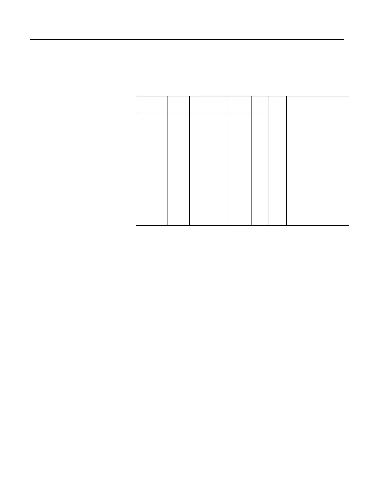
Digital Output Configuration
Usage Access T Data Type Default Min Max Semantics of Values
Optional - All Set
REAL []=0 - - Enumeration:
0 = Unassigned
1 = Contactor Enable
2 = Mechanical Brake
3 = Resistive Brake
4-255 = (reserved)
[ Axis 1 Output Config[8],
Axis 2 Output Config[8],
Axis 3 Output Config[8],
Axis 4 Output Config[8],
Axis 5 Output Config[8],
Axis 6 Output Config[8],
Axis 7 Output Config[8],
Axis 8 Output Config[8]]
This attribute is a 2 dimensional array of enumerated values that map configurable
digital output to specific functions for each drive axis. Each of the 8 possible axis
instances may support up to 8 configurable digital outputs. The Logix controller
distributes the Digital Output Configuration array elements to each axis instance
of the device. The Digital Output Configuration attribute in the device is defined
as a 32 element array of which only the first 8 elements are supported by this 8x8
Digital Output Configuration array definition. The remaining elements of the 32
element array are set to 0.

 Loading...


