(18)
DIR 1000587R0002 (Version 02)
Ref. Description
1 Phase current measurement
2 CB and/or trip unit alarms (sinewave logo appears in the absence of alarms)
3 Internal clock
4 “Low Power“ message
5 Operating icons
6 Graphic ammeter and voltmeter
7 Rms value and highest measured current phase (cyclically updated value)
8 Name of the menu being browsed
9 List of options available in the menu being browsed (the value that appears in black is the one that has been selected)
10 Number of options available in the menu being browsed
11 Value or description of the selected option
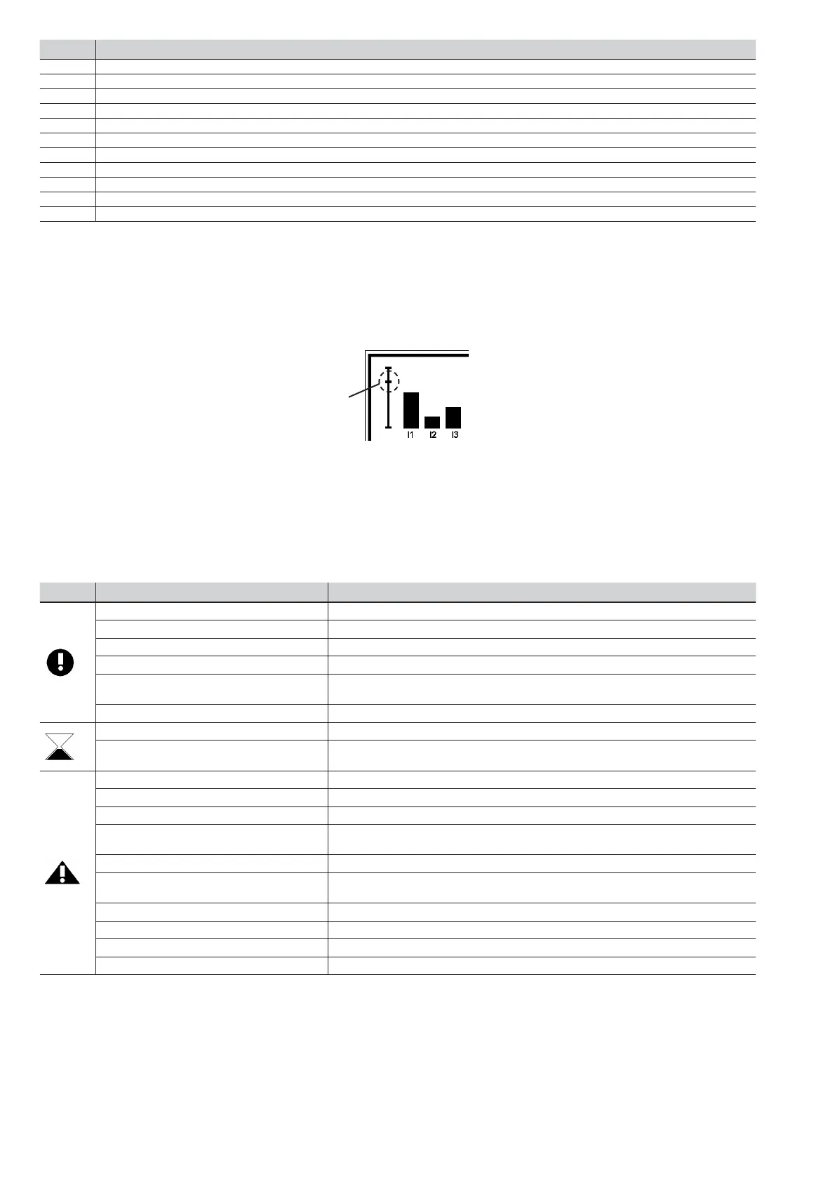
3.4.3.1. Graphic ammeter
Graphic ammeter option is available in the default page.
The levels of the available measurements are displayed by a vertical bar.
The current (phase) values are positioned along the abscissae, with the reference and rated value setting along the ordinate: an
intermediate line indicates the 1In value for the current values.
1In
Example: if the bar corresponding to current I1 exceeds the intermediate line, it means that the measured value is higher than 1In.
3.4.3.2. CB and trip unit alarms
Information about the state of the trip unit and CB is always available at the bottom left of the display (See par. 3.4.3 Display Ref.2).
The sinewave logo appears in the absence of alarms.
If one or more alarms have occurred, they will be displayed by a message that fl ashes every 2 seconds. The alarms are displayed
in conjunction with an icon showing the type of alarm in question (information, active delay, danger).
Icon Message Description
Confi guration Inconsistent parameters or inconsistent data between key plug and trip unit
Prealarm [L] / [T] Prealarm condition of the specifi ed protection. Example: “Prealarm L”
Warning Iw Iw threshold exceeded
Contact wear Contact wear prealarm (>80%)
Date not valid Incorrect date that must be programmed (new trip unit that has been off for
over 48h)
CB not defi ned “Open/closed” circuit-breaker state inconsistent or incorrect
Alarm T Internal temperature of trip unit off-range (<-25° or >85°)
Time delay [L] / [S] / [G] / [U] Time delay condition of the specifi ed protection, which can conclude with
an opening command transmitted to the CB.
Contact wear Alarm for contact wear (=100%)
Harmonic distortion Alarm for measured harmonic distortion (form factor>2.1)
[G] / [T] (TRIP OFF) Alarm of the specifi ed protection, of which the trip function has been disabled.
Alarm [U] Alarm of the specifi ed protection, of which the trip function has been disabled
or if the trip is activated but the CB is already open
Load [LC1] / LC2] Load control alarm. Example: “Load LC2“
Sensor [L1] / [L2] / [L3] / [Ne] Alarm of the specifi c current sensor (disconnected or faulty). Example:
“sensor L3“
TC disconnected Trip Coil disconnected or faulty
Rating Plug Rating plug absent, disconnected, faulty or of a model superior to the lu
Installation Error following an incorrect installation procedure or failure to install
Power factor Power factor module lower than set limit
 Loading...