(25)
DIR 1000587R0002 (Version 02)
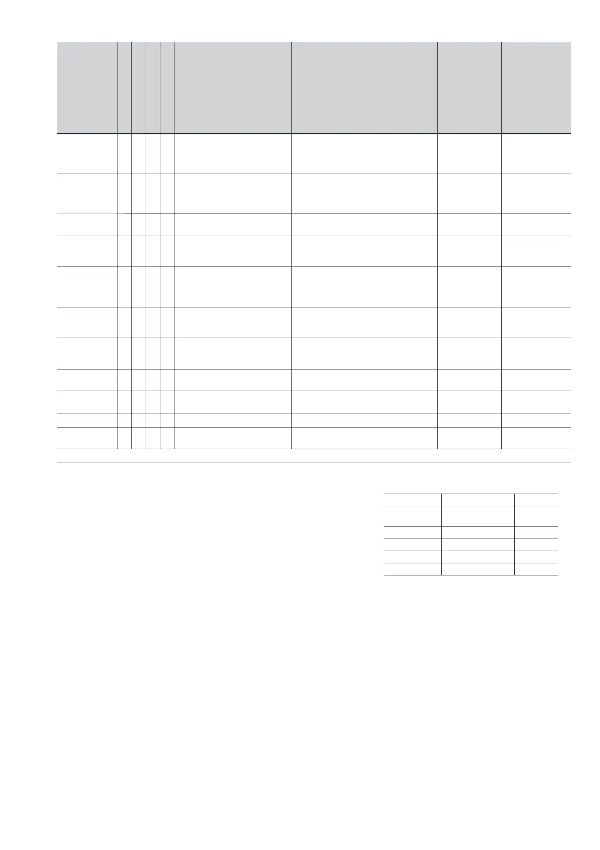
3.6.12. Summary table of protection functions
Current
protections
Disabling
Disabling of TRIP only
Start-up threshold
Thermal memory
Trip Threshold Trip time
Trip
threshold
tolerance
(2)
Trip time
tolerance
(2)
L
all curves:
t=k/I2 and
IEC 60255-3
0.4xIn
I
1
1xIn
step 0.01xIn
3s t
1
144s
(1)
, step 3s
@I
f
=3I
1
Release
between 1.05
and 1.2 xI1
±10%, I
f
6In
±20%, I
f
6In
S
(t=k)
0.6xIn I
2
10xIn
step 0.1xIn
0.6xIn I
2 start-up
10xIn
step 0.1xIn
I
f
>I2
0.05s t
2
0.8s, step 0.01s
0.10s t
2 start-up
30s, step 0.01s
0.04s t
2 sel
0.2s, step 0.01s
±7%, I
f
6In
±10%, I
f
> 6In
The best of the
two data±10%
or 40ms
S
(t=k/I
2
)
0.6xIn
I
2
10xIn
step 0.1xIn
0.05s t
2
0.8s,
step 0,01 s @I
f
=10In
±7%, I
f
6In
±10%, I
f
> 6In
±15%, I
f
6In
±20%, I
f
6In
I
(t=k)
1.5xIn
I
3
15xIn
step 0.1xIn
1.5xIn I
3 Start-Up
15x In
30 ms
0.1s t
3 start-up
30s, step 0.01s
@ I
f
>I
3
±10%
G
(3) (4)
(t=k)
0.1xIn I
4
1xIn
step 0.02xIn
0.1s t
4
1s, step 0.05 s
0.1s t
4 start-up
1s, step 0.02s
0.04s t
4 sel
0.2s, step 0.01s
@ I
f
>I
4
±7%
The best of the
two data±10%
or 40ms
G
(3) (4)
(t=k/I
2
)
0.1xIn I
4
1xIn
step 0.02xIn
0.2xIn I
4 Start-Up
1x I
4
0,1s t
4
1s, step 0.05s
(minimum trip time)
@I
f
>4In
±7% ±15%
U
(t=k)
2% I
6
90%
step 1%
0.5s t
6
60s, step 0.5s ±10%
The best of the
two data±10%
or 40ms
OT
(temp=k)
Fixed Instantaneous ± 5°C
LC1/LC2
load Control
50%100% step 1%xI
1
Warning Iw
0.310I
n
step 0.05xI
n
± 10% 1040 ms
MM
(t=k)
1.5xIn I
5
4xIn
step 0.1xIn
30 ms
@ I
f
>I
5
±10%
(1)
The minimum value of this trip is 1s regardless of the type of curve set (self-protection).
(2)
These tolerances are based on the following assumptions:
- energized trip unit in service conditions (without start-up) with 2 or 3 phases energized and/or
in the presence of auxiliary supply.
- Preset trip time 100 ms.
- Temperature and currents inside working ranges.
(3)
Protection G can be automatically disabled by the trip unit on the basis of the current measured.
For different cases see 3.6.5.
(4)
Minimum threshold for G protection, without Vaux, is 0.2 In.
For all cases not covered by the above hypotheses, the
following tolerance values apply:
Protection Trip threshold Trip time
L
Release between
1.05 e 1.25 x I1
± 20%
S ± 10% ± 20%
I MM ± 15% 60ms
G ± 10% ± 20%
Others ± 20%
 Loading...