Rockwell Automation Publication 2080-UM005B-EN-E - March 2015 93
Using microSD Cards Chapter 9
Datalog Function Block Execution
• There are three possible states for the Datalog function block: Idle,
Busy and Complete (which includes Complete with Succeed and
Complete with Error).
• For one Datalog function block execution, the typical status starts
from Idle, then Busy and finishes with Complete. To trigger another
function block execution, the status needs to go back to Idle first.
• Idle status changes to Busy status only when Enable input signal is in
rising edge. Complete status enters Idle status when Enable input
signal is Disable status only.
• TSEnable and CfgId input parameters are only sampled at Enable
input parameter's rising edge when a new function block execution
starts. During function block execution, the input parameters of
TSEnable and CfgId are locked and any changes are ignored.
• When execution completes, the status changes from Busy to
Complete. At this stage, if input Enable is False, status changes to
Idle after indicating Complete for exactly one scan time. Otherwise
function block status is kept as Complete until input Enable changes
to False.
• The datalog file can only be created by the DLG instruction block.
Connected Components Workbench can only upload and delete the
datalog file.
• There are separators in between every data variable in the data file
which is defined during configuration in Connected Components
Workbench.
See Supported Data Types for Datalog and Recipe Function Blocks
on
page 93.
• Data variable values are sampled when datalogging function block is
in Busy state. However, datalogging file is only created when
datalogging function block is in Complete state.
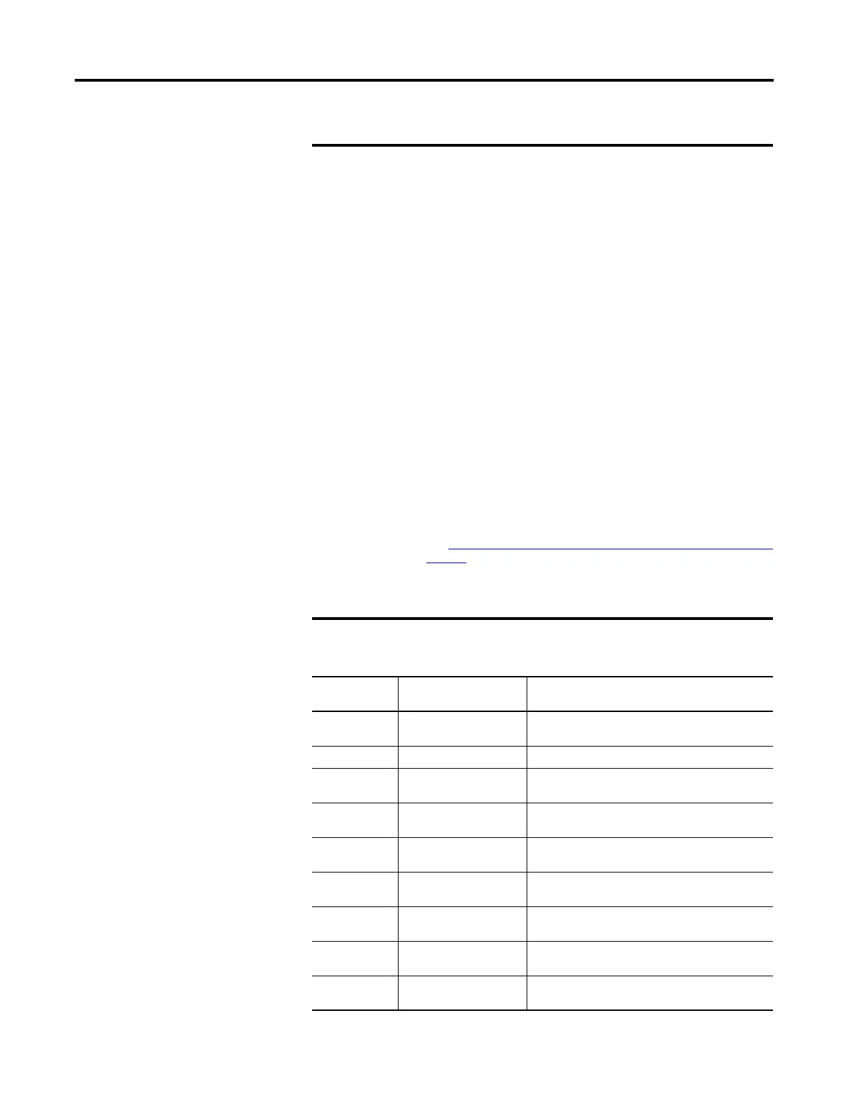
Supported Data Types for Datalog and Recipe Function Blocks
Data Type Description Example format in output
datalog file
BOOL
(1)
Logical Boolean with
values TRUE and FALSE
0: FALSE
1: TRUE)
SINT Signed 8-bit integer value -128, 127
INT Signed 16-bit integer
value
-32768, 32767
DINT Signed 32-bit integer
value
-2147483648, 2147483647
LINT Signed 64-bit integer
value
-9223372036854775808, 9223372036854775807
USINT(BYTE) Unsigned 8-bit integer
value
0, 255
UINT(WORD) Unsigned 16-bit integer
value
0, 65535
UDINT(DWORD) Unsigned 32-bit integer
value
0, 4294967295
ULINT(LWORD) Unsigned 64-bit integer
value
0, 18446744073709551615

 Loading...


