Rockwell Automation Publication 2080-UM005B-EN-E - March 2015 39
Wire Your Controller Chapter 4
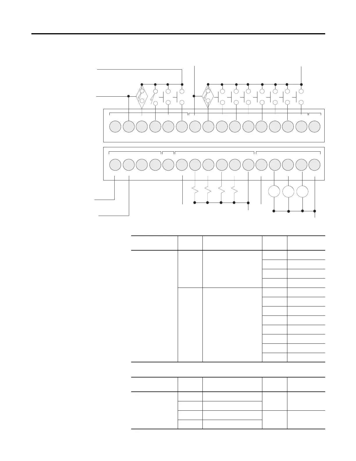
DC Sourcing Input Configuration – Inputs 4...11
-DC24
+DC10 I-00
I-01
I-02
I-03
COM0
I-04
I-05
I-08
I-07
123456789101112
+DC24 -DC24
VO-0-DC24
NU
+CM0
O-00
O-01 O-03
O-02
+CM1
-CM0
123456789101112
I-10
I-09
NU
I-11
13 14 15 16
O-05
O-04
-CM1
O-06
13 14 15 16
I-06
+DC b
-DC a
+DC a
-DC b
+DC c
-DC c
+DC d
-DC d
-DC e
CR
CR CR
+DC e
Digital Input
Controller Terminal
Number
Input Common
Terminal Label
Terminal
Number
Input Terminal
Label
2080-LC20-20QBB,
2080-LC20-20QBBR
2 “-DC24” (24V DC sink only) 3 I-00
4I-01
5I-02
6I-03
7 CM0 (24V DC sink/source) 8 I-04
9I-05
10 I-06
11 I-07
12 I-08
13 I-09
14 I-10
15 I-11
Digital Output
Controller Terminal
Number
Input Common
Terminal Label
Terminal
Number
Input Terminal
Label
2080-LC20-20QBB,
2080-LC20-20QBBR
6 +CM0 (VDC source) 7, 8, 9, 10 O-00, O-01, O-02,
O-03
11 -CM0
12 +CM1 (VDC source) 13, 14, 15 O-04, O-05, O-06
16 -CM1
 Loading...


