38 Rockwell Automation Publication 2080-UM005B-EN-E - March 2015
Chapter 4 Wire Your Controller
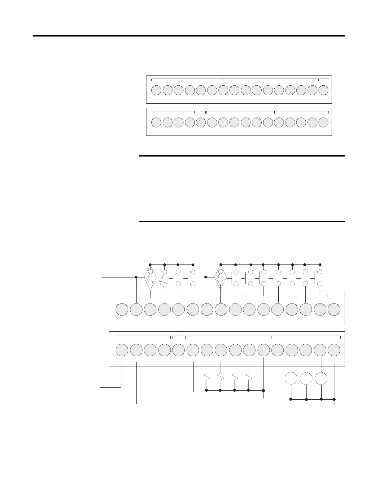
2080-LC20-20QBB / 2080-LC20-20QBBR
DC Sinking Input Configuration – Inputs 00...11
Note the following:
• The “-DC24” terminals on the Input (terminal 2) and Output (terminals
2 and 3) Terminal Blocks are internally shorted.
• “NU” means that the terminal is not used / no connection.
• Inputs I-00, I-01, I-02, and I-03 are shared between digital and analog
inputs.
• Inputs I-00, I-01, I-02, and I-03 can only be used in sinking input
configuration.
-DC24
+DC10 I-00
I-01
I-02
I-03
COM0
I-04
I-05
I-08
I-07
123456789101112
+DC24 -DC24
VO-0-DC24
NU
+CM0
O-00
O-01 O-03
O-02
+CM1
-CM0
123456789101112
I-10
I-09
NU
I-11
13 14 15 16
O-05
O-04
-CM1
O-06
13 14 15 16
I-06
46211
Input Terminal Block
Output Terminal Block
-DC24
+DC10 I-00
I-01
I-02
I-03
COM0
I-04
I-05
I-08
I-07
123456789101112
+DC24 -DC24
VO-0-DC24
NU
+CM0
O-00
O-01 O-03
O-02
+CM1
-CM0
123456789101112
I-10
I-09
NU
I-11
13 14 15 16
O-05
O-04
-CM1
O-06
13 14 15 16
I-06
-DC b
-DC a
+DC a
+DC b
+DC c
-DC c
+DC d
-DC d
-DC e
CR
CR CR
+DC e
 Loading...


