Preface
MicroLogix 1000 Programmable Controllers User Manual
1–6
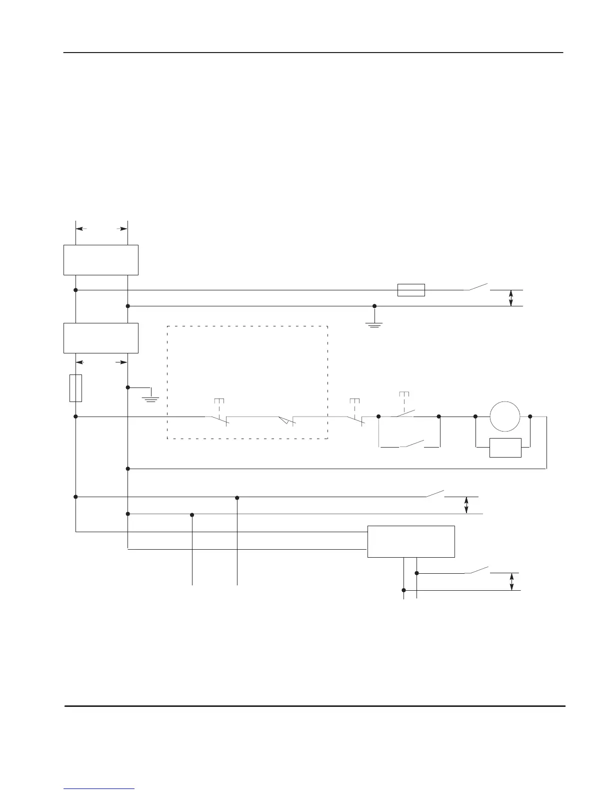
The following illustrations show the Master Control Relay wired in a grounded
system.
Note The
illustrations only show output cir
cuits with MCR pr
otection. In most
applications input cir
cuits do not r
equire MCR pr
otection; however
, if you need to
r
emove power fr
om all field devices, you must include MCR contacts in series with
input power wiring.
Schematic (Using IEC Symbols)
X1
230V ac
230V ac
Disconnect
Isolation
Transformer
Operation of either of these contacts will
remove power from the adapter external I/O
circuits, stopping machine motion.
MCR
MCR
MCR
Emergency-Stop
Push Button
Overtravel
Limit Switch
Stop
Start
Suppr.
MCR
(Lo) (Hi)
Line T
erminals: Connect to 230V ac
terminals of Power Supply
.
dc Power Supply
.
Use IEC 950/EN 60950
MCR
+
—
X2
Line terminals: Connect to 24V dc
terminals of Power Supply
.
24V dc
I/O Circuits
230V ac
I/O Circuits
230V ac
I/O Circuits
Master Control Relay (MCR)
Cat. No. 700-PK400A1
Fuse
Fuse
Suppressor
Cat. No. 700-N24
efesotomasyon.com - Allen Bradley,Rockwell,plc,servo,drive

 Loading...


