EasyManuals Logo

Allen-Bradley MicroLogix 1000 User Manual

Allen-Bradley MicroLogix 1000
422 pages
To Next Page IconTo Next Page
To Previous Page IconTo Previous Page
Page #23 background imageLoading...
Page #23 background image
Hardware
Installing
Y
our Controller
1–7
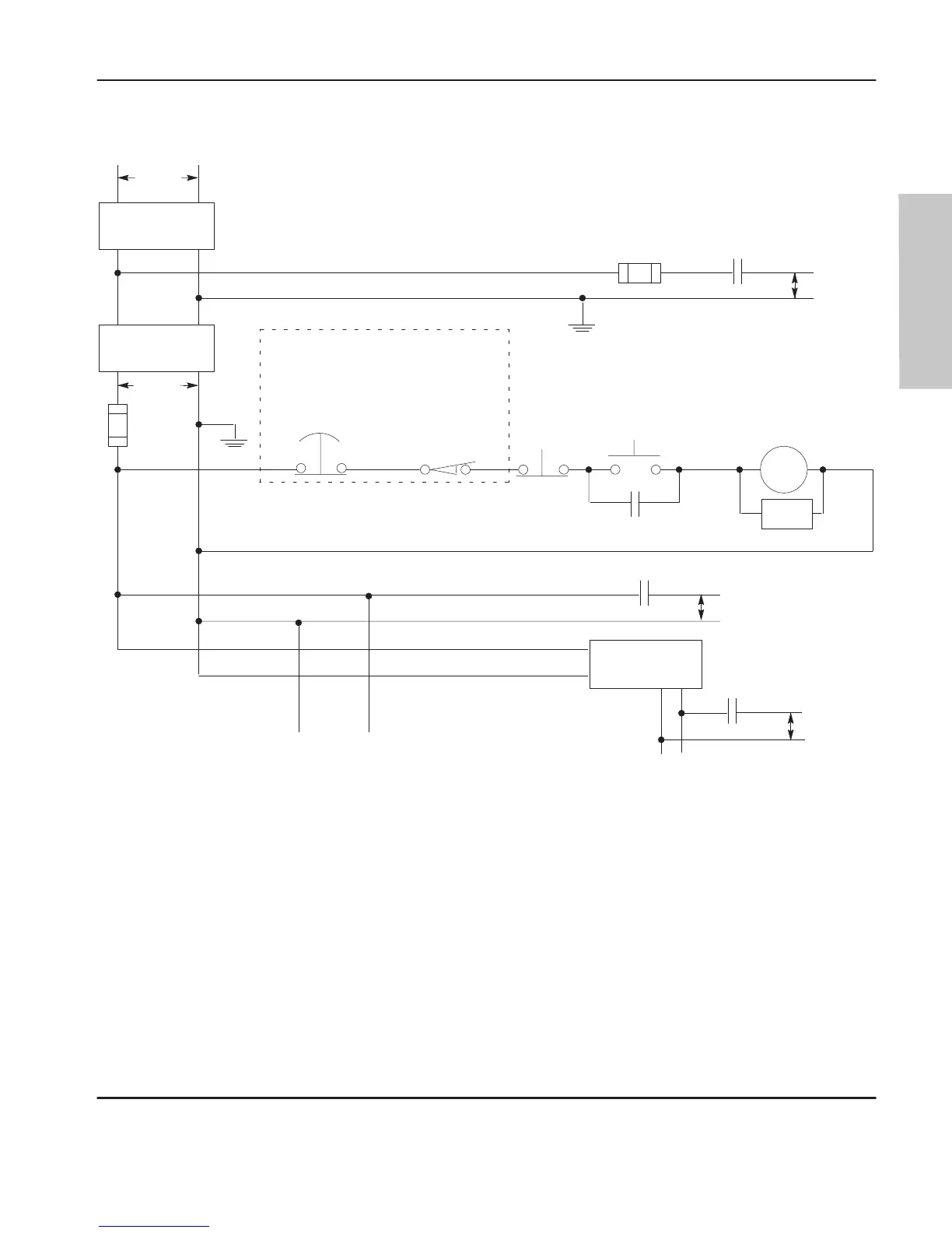
Schematic (Using ANSI/CSA Symbols)
115V ac
230V ac
Disconnect
L1 L2
Isolation
Transformer
Fuse
Operation of either of these contacts will
remove power from the adapter external I/O
circuits, stopping machine motion.
MCR
MCR
MCR
Emergency-Stop
Push Button
Overtravel
Limit Switch
Stop
Start
Suppr.
MCR
(Lo) (Hi)
Line T
erminals: Connect to 1
15V ac
terminals of Power Supply
.
dc Power Supply
.
Use N.E.C. Class 2
for UL Listing.
MCR
+
X1
X2
Line terminals: Connect to 24V dc
terminals of Power Supply
.
24V dc
Output
Circuits
1
15V ac
Output
Circuits
230V ac
Output
Circuits
Master Control Relay (MCR)
Cat. No. 700-PK400A1
Fuse
Suppressor
Cat. No. 700-N24
efesotomasyon.com - Allen Bradley,Rockwell,plc,servo,drive

Table of Contents

Questions and Answers:

Question and Answer IconNeed help?

Do you have a question about the Allen-Bradley MicroLogix 1000 and is the answer not in the manual?

Allen-Bradley MicroLogix 1000 Specifications

General IconGeneral
Communication PortsRS-232
Power Supply24V DC or 120/240V AC
Programming SoftwareRSLogix 500
ManufacturerAllen-Bradley
CategoryController
SeriesMicroLogix
Programming LanguageLadder Logic
Input Voltage24V DC or 120/240V AC
I/O Points10 to 32 points
Processor Type8-bit
Operating Temperature0…55 °C (32…131 °F)
Processor8-bit

Related product manuals