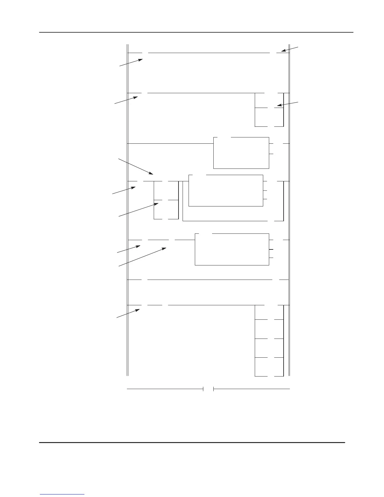
Using the Message Instruction
13–15
(U)
B3
0
(EN)
(DN)
(ER)
MSG
READ/WRITE MESSAGE
Read/write WRITE
Target Device SLC500/ML1000
Control Block N7:10
Control Block Length 7
END
0
2
*
MSG instruction
status bits:
13 = DN
15 = EN
]/[
N7:0
0
(L)
B3
0
( )
N7:0
1
(RES)
T4:0
(EN)
(DN)
TON
TIMER ON DELAY
Timer T4:0
Time Base 0.01
Preset 400
Accum 0
Temperature-sensing
Input Device
S:1
15
] [
S:4
6
3
] [
B3
0
(L)
N7:0
0
] [
S:1
15
] [
S:0
11
(EN)
(DN)
(ER)
MSG
READ/WRITE MESSAGE
Read/write READ
Target Device SLC500/ML1000
Control Block N7:21
Control Block Length 7
] [
N7:10
13*
] [
T4:0
DN
] [
N7:21
13*
(U)
B3
0
(RES)
T4:0
(U)
N7:0
0
(U)
N7:21
(U)
N7:10
15*
Operation
notes appear on the following page.
4
5
6
7
Bit 1 of the message
word. Used for fan
control.
Bit 0 of the
message word.
This is the interlock
bit.
4-second T
imer
W
rite message
instruction. The source
and target file addresses
are N7:0
T
arget node: 3
Message length: 1 word.
Read message
instruction. The
destination and target file
addresses are N7:0
T
arget node: 3
Message length: 1 word.
Latch – This alarm
instruction notifies the
application if the
interlock bit N7:0/0
remains set for more
than 4 seconds.
First Pass Bit
First Pass Bit
1280 ms Clock Bit
Message W
rite
Done Bit
Message Read
Done Bit
1
(L)
B3
10
] [
I:1.0
5
DH-485 Active
Protocol Bit
] [
S:0
11
DH-485 Active
Protocol Bit
] [
15*
efesotomasyon.com - Allen Bradley,Rockwell,plc,servo,drive
 Loading...


