Preface
MicroLogix 1000 Programmable Controller User Manual
13–16
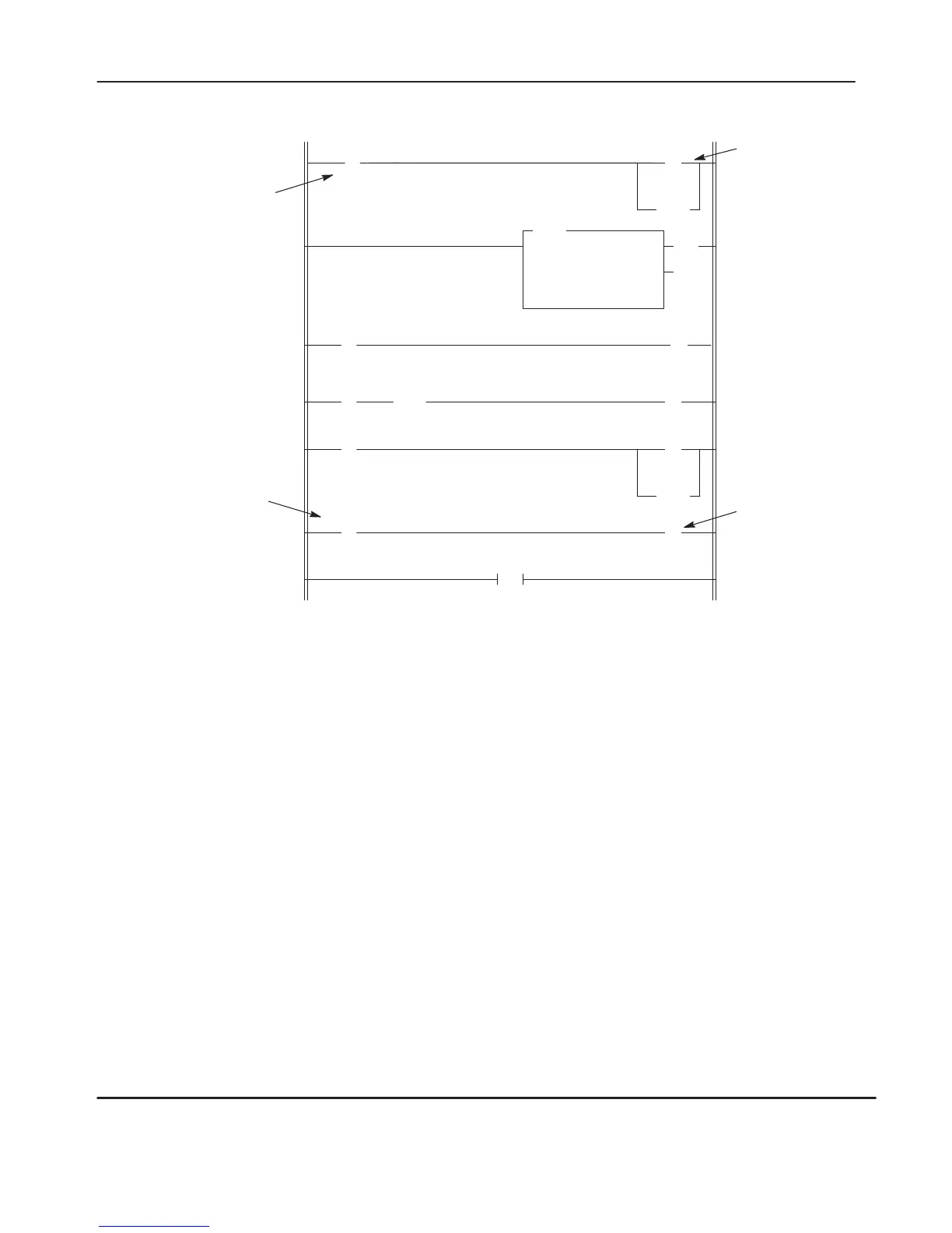
Program File 2 of SLC 5/01 Processor at Node 3
Operation Notes, MicroLogix 1000 and SLC 5/01 programs
MicroLogix 1000 controller: N7:0/0 is latched; timer T4:0 is
reset; B3/0 is unlatched (rung 1), then latched (rung 3).
SLC 5/01 processor: N7:0/0 is unlatched; timer T4:0 is reset.
Message instruction operation: The message write instruction in
the MicroLogix 1000 controller is initiated every 1280 ms by
clock bit S:4/6. The done bit of the message write instruction
initiates the message read instruction.
B3/0 latches the message write instruction. B3/0 is unlatched
when the message read instruction done bit is set, provided that
the interlock bit N7:0/0 is reset.
Communication failure: In the MicroLogix 1000 controller
, bit
B3/10 becomes set if interlock bit N7:0/0 remains set (1) for
more than 4 seconds. In the SLC 5/01 processor
, bit B3/10
becomes set if interlock bit N7:0/0 remains set (1) for more than
4 seconds. Y
our application can detect this event, take
appropriate action, then unlatch bit B3/10.
(U)
N7:0
0
END
0
( )
B3
1
(RES)
T4:0
(EN)
(DN)
TON
TIMER ON DELAY
Timer T4:0
Time Base 0.01
Preset 400
Accum 0
] [
N7:0
0
First Pass Bit
[OSR]
B3
0
] [
T4:0
DN
] [
B3
1
(U)
N7:0
0
(RES)
T4:0
( )
O:1.0
0
] [
N7:0
1
1
3
6
Bit 0 of the message
word. This is the
interlock bit.
4-second T
imer
Latch Instruction –
This alarm notifies the
application if the interlock
bit N7:0/0 is not set after
4 seconds.
O:1/0 energizes
cooling fan.
Bit 1 of the message
word. Used for fan
control.
Message instruction parameters: N7:0 is the message word. It
is the target file address (SLC 5/01 processor) and the local
source and destination addresses (MicroLogix 1000 controller)
in the message instructions.
N7:0/0 of the message word is the interlock bit; it is written to
the 5/01 processor as a 1 (set) and read from the SLC 5/01
processor as a 0 (reset).
N7:0/1 of the message word controls cooling fan operation; it is
written to the SLC 5/01 processor as a 1 (set) if cooling is
required or as a 0 (reset) if cooling is not required. It is read
from the SLC 5/01 processor as either 1 or 0.
W
ord N7:0 should have a value of 1 or 3 during the message
write execution. N7:0 should have a value of 0 or 2 during the
message read execution.
Program initialization: The first pass bit S:1/15 initializes the
ladder programs on run mode entry
.
(L)
B3
10
4
5
2
] [
S:1
15
efesotomasyon.com - Allen Bradley,Rockwell,plc,servo,drive

 Loading...


