Programming
Using the Message Instruction
13–17
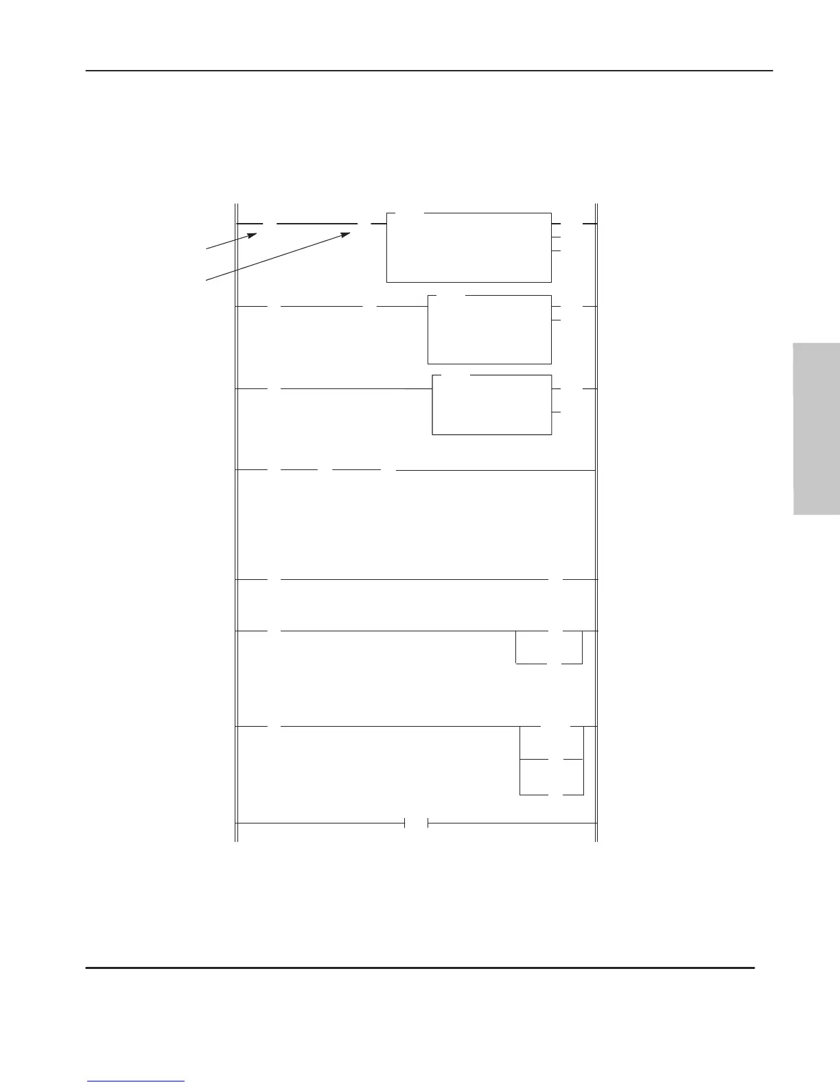
Example 4
Application
example 4 shows you how to use the timeout bit to disable an active
message instruction. In this example, an output is ener
gized after five unsuccessful
attempts (two seconds duration) to transmit a message.
The
timeout bit is latched (rung 4) after a period of 2 seconds.
This clears the message instruction from processor control on
the next scan. The message instruction is then re-enabled for a
second attempt at transmission. After 5 attempts, O:1/0 is
latched and B3/1 is unlatched.
A successful attempt at transmission resets the counter
, unlatches
O:1/0, and unlatches B3/1.
END
0
(EN)
(DN)
(ER)
MSG
READ/WRITE MESSAGE
Read/write WRITE
Target Device SLC500/ML1000
Control Block N7:0
Control Block Length 7
] [
N7:0
14
(EN)
(DN)
TON
TIMER ON DELAY
Timer T4:0
Time Base 0.01
Preset 200
Accum 0
] [
B3
1
(CU)
(DN)
CTU
COUNT UP
Counter C5:0
Preset 5
Accum 0
N7:0
8
(RES)
C5:0
(L)
N7:0
(U)
B3
1
(L)
O:1.0
0
] [
B3
1
] [
T4:0
DN
] [
C5:0
DN
] [
N7:0
13*
1
2
3
5
6
7
*
MSG instruction
status bits:
8 = TO
12 = ER
13 = DN
2-second timer
. Each
attempt at transmission
has a 2-second duration.
Counter allows 5
attempts.
N7:0/8* is the message
instruction timeout bit.
After timeout error
,
unlatch the MSG EN bit to
retrigger for another
attempt.
The fifth attempt latches
O0:1/0 and unlatches the
initiate message
instruction bit.
B3/1 is latched
(external to this
example) to initiate the
message instruction.
] [
T4:0
DN
4
] [
Operation Notes
8
(U)
O:1.0
0
*
] [
N7:0
12
] [
S:0
11
DH-485 Active
Protocol Bit
(U)
B3
1
N7:0
15
(U)
efesotomasyon.com - Allen Bradley,Rockwell,plc,servo,drive

 Loading...


