Hardware Reference
A–7
Input Filter Response Times (Discrete)
The input filter response time is the time from when the external input voltage
reaches an on or off state to when the micro controller recognizes that change of
state. The higher you set the response time, the longer it takes for the input state
change to reach the micro controller. However
, setting higher response times also
provides better filtering of high frequency noise.
You can apply a unique input filter setting to each of the three input groups:
• 0 and 1
• 2 and 3
• 4 to x; where x=9 for 16 I/O point controllers, and x=19 for 32 I/O point
controllers
The minimum and maximum response times associated with each input filter setting
can be found in the tables that follow.
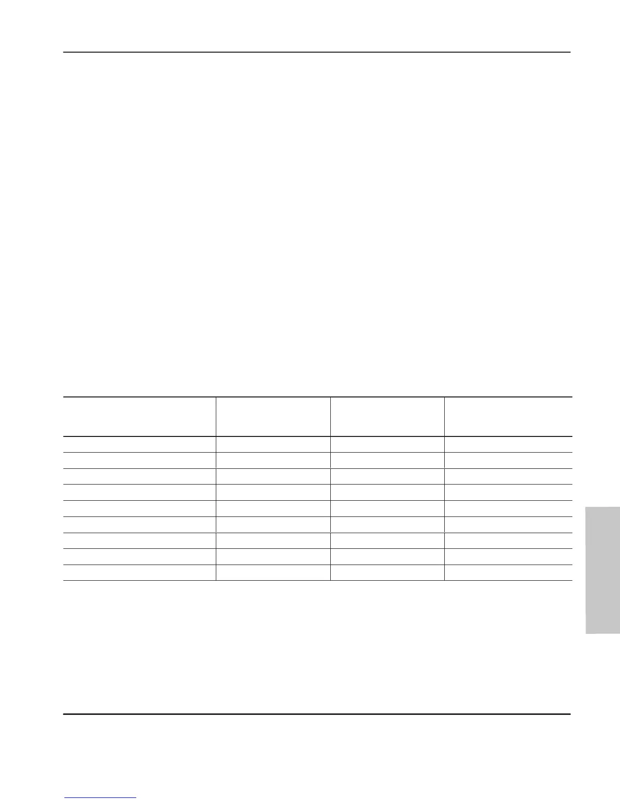
Response Times for High-Speed dc Inputs 0 to 3 (applies to 1761-L10BWA, 1761-L16BWA,
-L20BWA-5A, -L32BWA, -L10BWB, -L16BWB, -L20BWB-5A, -L32BWB, -L16BBB, and
-L32BBB controllers)
Maximum High-Speed Counter
Frequency @ 50% Duty Cycle
(Khz)
Nominal Filter
Setting (ms)
Maximum ON
Delay (ms)
Maximum OFF
Delay (ms)
6.600 0.075 0.075 0.075
5.000 0.100 0.100 0.100
2.000 0.250 0.250 0.250
1.000 0.500 0.500 0.500
0.500 1.000 1.000 1.000
0.200 2.000 2.000 2.000
0.125 4.000 4.000 4.000
0.062
8.000
➀
8.000 8.000
0.031 16.000 16.000 16.000
➀
This is the default setting.
Reference
efesotomasyon.com - Allen Bradley,Rockwell,plc,servo,drive

 Loading...


