Preface
MicroLogix 1000 Programmable Controllers User Manual
3–8
The
table below shows connections for Belden #3106A.
For
this W
ire/Pair
Connect this W
ire To this Terminal
Shield/Drain Non-jacketed T
erminal 2 – Shield
Blue Blue T
erminal 3 – (Common)
White with Orange Stripe
T
erminal 4 – (Data B)
White/Orange
Orange with White Stripe
T
erminal 5 – (Data A)
The
table below shows connections for Belden #9842.
For
this W
ire/Pair
Connect this W
ire To this Terminal
Shield/Drain Non-jacketed T
erminal 2 – Shield
White with Blue Stripe
Cut back – no connection
➀
Blue/White
Blue with White Stripe
T
erminal 3 – (Common)
White with Orange Stripe
T
erminal 4 – (Data B)
White/Orange
Orange with White Stripe
T
erminal 5 – (Data A)
➀
T
o prevent confusion when installing the communication cable, cut back the white with blue stripe wire
immediately after the the insulation jacket is removed. This wire is not used by DH-485.
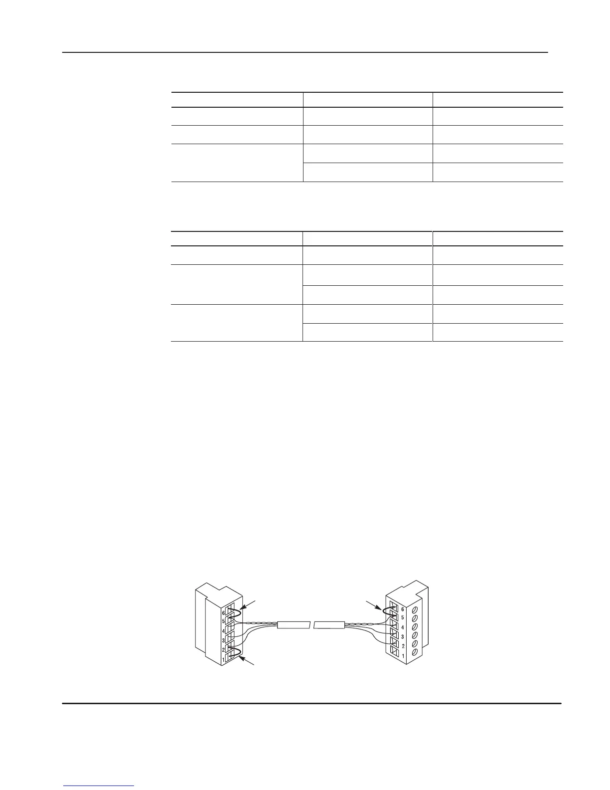
Grounding and Terminating the DH-485 Network
Only one connector at the end of the link must have Terminals 1 and 2 jumpered
together. This provides an earth ground connection for the shield of the
communication cable.
Both ends of the network must have Terminals 5 and 6 jumpered together. This
connects the termination impedance (of 120Ω
) that is built into each AIC+ as
required by the DH-485 specification.
End-of-Line Termination
Belden
#3106A or #9842 Cable
1219 m (4000 ft) Maximum
Jumper
Jumper
Jumper
efesotomasyon.com - Allen Bradley,Rockwell,plc,servo,drive

 Loading...


