Connecting the System
3–15
Powering the AIC+
If you use an external power supply, it must be 24V dc. Permanent damage
will result if miswired with the wr
ong power sour
ce.
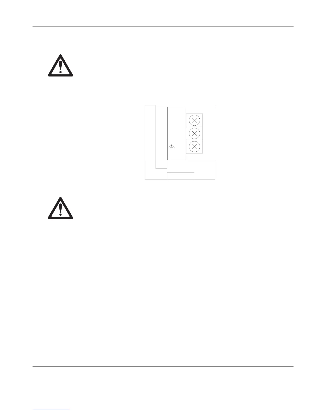
Set the DC Power Source selector switch to EXTERNAL before connecting the
power supply to the AIC+.
24VDC
DC
NEUT
CHS
GND
Bottom
V
iew
Always connect the CHS GND (chassis ground) terminal to the nearest earth
ground. This connection must be made whether or not an external 24V dc
supply is used.
In normal operation with the MicroLogix 1000 programmable controller connected
to port 2 of the AIC+, the controller powers the AIC+. Any AIC+ not connected to
a controller requires a 24V dc power supply. The AIC+ requires 104 mA at 24V dc.
If both the controller and external power are connected to the AIC+, the power
selection switch determines what device powers the AIC+.
efesotomasyon.com - Allen Bradley,Rockwell,plc,servo,drive

 Loading...


